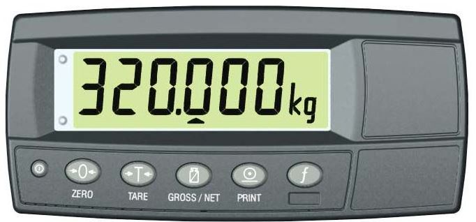
Rinstrum R320 Digital Truck Scale
About Rinstrum
Rinstrum is a company that specializes in the design and manufacturing of weighing systems and solutions. They are known for producing a wide range of weighing and measurement equipment, including scales, load cells, indicators, and software for various industrial and commercial applications.
Rinstrum’s products are used in industries such as agriculture, logistics, manufacturing, healthcare, food processing, and more. They offer a variety of weighing solutions to meet the diverse needs of their customers.
General Features
- A user-friendly system with built-in troubleshooting diagnostics and our 24-7 technical support line is available. 307-321-4505
- The system is designed to work dependably and accurately in the harshest environments,
- The accumulation feature allows operators to count up for total or display single load weight.
- It is accurate and requires less than an hour to install and calibrate
- RS232 Printer accessory available providing weight, date, time, and total weight.
- Two Setpoints with Isolated 300mA 50V Outputs
- Internal Clock/Calendar
Technical Features
- Input Power – Voltage: 9 – 18Vdc
- Input Power – Current/Amps: Maximum: 500mA Input
- Power – Current/Amps: Nominal: 150mA
- Excitation Voltage: 5Vdc
- Operating Temperature: 14F to 104F (10C to 40C)
- Control Panel Key Functions: Power/Units, ZERO, Tare, Select, Print, Function
- Serial Port: Full Duplex RS-232 format
- DisplayTechnology: 6-digit LCD 3/4″ height
- Housing Material: Grey ABS Weight: 1 lb. 6oz.
- Shipping Weight: 2 1b. 4oz.
Options and Accessories
- Receipt Printer
- Remote Switch for Accumulator Function
- 12Vdc Battery Line Conditioner
- Voltage-Converter for 24 Volt to 48Volt systems)
- The SEKO Forklift Scale Modular Load Cell weighing system determines the load weight by sensing the weight on the forks.
- This signal is transmitted to the In-Cab Indicator, which displays the weight of the forks.
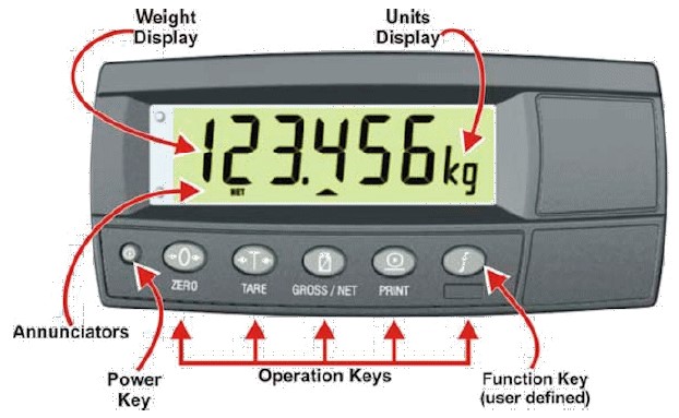
Rinstrum R320 Scale Indicator Face View
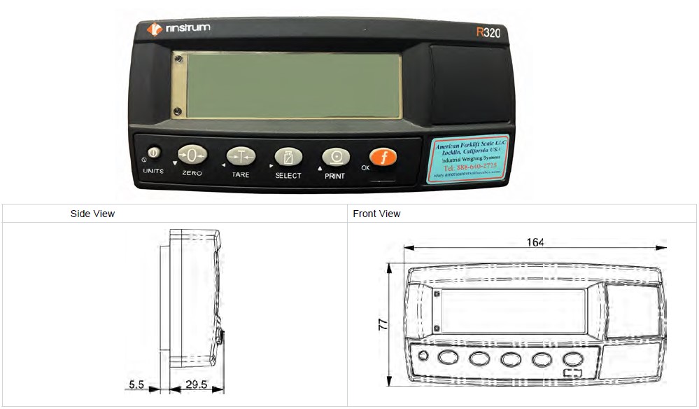
Rinstrum R320 Scale Indicator Rear View

Electrical Installation
Rinstrum R320 Scale Indicator Power: 9Vdc to 18Vdc from Truck Electrical. Power may be attached via an external plug or hardwired to an internal Euro connector. Connect power via the Key Switch or directly to Battery Power.

Recommended in-line fuse for truck electrical protection: 2.0A Minimum. For 24, 36, and 48Vde truck electrical systems, contact Sales for Power Converter recommendations.
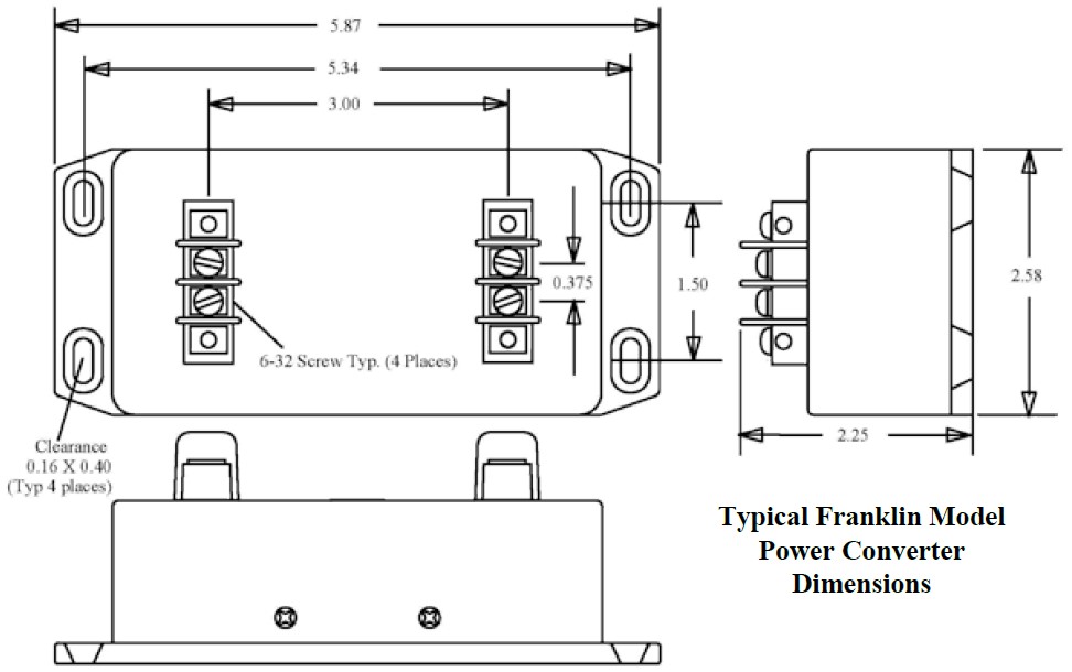
Standard Rinstrum Rear Panel Wiring Options

R-320 Indicator Rinstrum KT-40 Printer Wiring

R-320 Indicator Rear Panel Wiring with Remote Alarm Cable and Jumper

- Install jumper (provided in Alarm Kit) from PWR (+) to COM
- Connect Alarm Cable RED wire to OUT 1
- Connect Alarm Cable BLACK Wire to GND
- Check to ensure spring-clips grip wire, no insulation
Operator Briefing Weighing Methods
A simple weighing procedure that produces desired weight consistency and accuracy:
Simply “Lift and Weigh”:
- Load the forks and lift
- Allow the scale to calculate and display the weight of the load.
Weighing liquid, dangling, and hanging loads:
- Liquid, dangling, and hanging loads can be difficult to weigh because the shifting load produces unstable inertial and gravitational stresses on the lifting mechanics.
- Try to operate the truck to avoid sloshing, swinging, or bouncing off the load when lifting to weigh.
- The Rinstrum Indicator can be set up for “Live Weight” weighing of unstable loads, such as live animals. See Section 8.4.7 of the Reference Manual for setup and weighing details.
Operator Briefing What is “Scale Weighing Accuracy”?
What does the term “Accurate” mean?
“Accurate” means that the scale displays the actual weight of the load, within the specified +/- tolerance of error, plus one display graduation, whichever is larger.
What do the terms “Consistent” and “Reliable” mean?
- “Consistent” means that the weights displayed are close in value and not “scattered”. We consider consistent and reliable weights to be those that vary less than +/- one scale display increment.
- “Reliable” relates to your level of confidence that the weighing system is producing a consistent and accurate weight display each time you lift and weigh.
What does the term “Scale Error” mean?
- Scale Error or Accuracy is defined as a percentage of full-scale capacity.
- SEKO Forklift Scale systems utilize Rinstrum’s NTEP-certified Scale Indicator producing display errors of less than +/- 0.03% and NTEP-certified S-beam type load cells producing signals with +/- 0.03% error.
- The SEKO weigh module low-friction mechanical design allows better than +/- 0.1% displayed weight error in practice.
- Mast tilt can cause weighing errors due to the altered gravitational vector producing strain on the scale load cells. In normal truck operations, this effect is small and generally not noticed.
- However, when +/- 0.1% accuracy is essential, we recommend that the Tilt Compensation scale option be considered. This option will automatically sense and correct the weight display for the effects of load tilt up to +/- 10 degrees of truck/mast and carriage tilt.
A Note to you, the Operator – Your operation experience is the basis for all that is written in these notes. Your feedback, comments, and recommendations are very important and can aid other operators as the information is passed along, such as we have done in these notes. I hope these comments have been useful for your work. Please feel free to call 307-321-4505 for additional assistance and to share experiences of success and not-so-successful. Your input will help improve these notes.
Passcodes and Operator Lock-Out
The instrument has two levels of passcodes to provide a restricted Setup via the keypad.
Full Setup Passcode
For calibration and Technician Access
- Setting a passcode for Full Setup restricts any access to Full Setup.
- A full Setup passcode can also be used to access Safe Setup.
Safe Setup Passcode
May allow limited Operator Access
- Setting a Passcode for Safe Setup restricts access to Safe Setup functions.
Setup Operator Lock-Out
- If an attempt is made to enter Full or Safe Setup using an incorrect Passcode, the instrument will respond with the message ENTRY DENIED and then the user will be returned to normal operating mode.
- A Passcode counter has been set so that only three failed attempts can be made to access Full/Safe Setup. On the fourth attempt, the user will be ‘locked out’ of the Full/Safe setup.
- Should this occur the ENTER PASS prompt will not display, but instead the ENTRY DENIED message will display and return the user to the normal operating mode. To rectify this issue the instrument must be turned off. When the instrument is turned back on the Passcode counter is reset to zero (allowing the user to enter the correct Passcode).
- SAFE.PC (Safe Passcode for Operator access.) allows partial access to Digital Setup (ie. only non-calibration/trade critical settings can be changed).
- For the Safe Passcode (SAFE.PC) to have any effect, the FULL.PC (Full Passcode) must also be set.
The default Passcode setting is 000000 which allows free access.
Any other number will restrict access.
- Range: 000000 to 999999
- Default: 000000
FULL.PC (Full Passcode) can be set to restrict access to Full Digital Setup. This Passcode is used to prevent unauthorized or accidental tampering in the instrument setup.
The default Passcode setting is 000000 allows free access.
Any other number will enable the Passcode functions and restrict access.
- Range: 000000 to 999999
- Default: 000000
It is important to note that when restricting Full access to Setup the Passcode must not be forgotten. It is only possible to circumvent the Passcode loss at the factory. Care must be taken when setting the Full Digital Setup Passcode to ensure that the instrument does not become permanently locked.
POWER CHECK and Troubleshooting
- POWER SOURCE
Check to be sure the system has primary DC power applied.
Power should be between 8Vdc and 18Vdc if powered from truck electrical or greater than 6Vdc using fresh “AA” batteries if utilizing an internal battery pack. - POWER-UP
Press the small UNITS (Power) button to turn on the Indicator.
The Indicator should show the Firmware version (A301 v4.16), then count down from 9 to 0 and then display READY.
PRIMARY POWER PROBLEMS
If the system does not turn ON or not stay ON, or if the system turns OFF unexpectedly:
- If no characters are displayed, if no backlight is seen, check the Primary Power wiring and connections.
• Truck power should be in the range of 11 to 13.8 Vdc.
• If a Voltage Converter is installed, Primary Power to the Indicator should be the labeled Output Voltage +/- 20%
• Check for correct Voltage polarity at the Indicator Connection.
• Note: Use a Voltmeter, if possible, to verify that the proper Voltage and polarity are present at all test points. - If the wiring to the scale indicator is equipped with a fuse, check the fuse.
• Note: The standard LTWS-1 hydraulic weighing systems normally consume less than 0.200 Amperes (200 milli-Amp).
• The purpose of an in-line fuse is to protect the truck’s electrical from a catastrophic short in the weighing system electronics and electrical wiring.
• This fuse rating should be in the range of 1.0 Amperes to 10 Amperes. - When measuring Primary Truck Voltage, the indicated Truck Voltage should not vary by more than about 0.1 V between when the indicator is turned ON and turned OFF.Truck electrical systems, especially older trucks, commonly utilize the truck frame as the common or negative connection to the battery. It is not unusual to experience high resistance caused by corrosion or loose fitting of the elements of the chassis between the battery terminal and the primary power to the indicator.
- This condition can produce an open circuit Voltmeter indication of satisfactory Voltage because the resistance of degraded continuity is difficult to detect in an open circuit. Degraded circuit/wire/ ground connections can often be detected by detecting the difference in Voltage at the load when OFF and when ON. Resistance of degraded connections will prevent full Voltage when the circuit load (Indicator) is ON.
- If possible, turn the Indicator ON and OFF while monitoring the primary power Voltage. Be alert for a significant drop in Voltage when the system is turned ON.
- For example, if the open circuit Voltage is 11.5 and drops to 10 V or 9.5 V etc. when the indicator is turned ON, this change is an indication that the system battery may need to be charged or that continuity of the conductors and connections between the battery to the indicator may have been degraded by corrosion or loosening, etc.
- This condition can produce an open circuit Voltmeter indication of satisfactory Voltage because the resistance of degraded continuity is difficult to detect in an open circuit. Degraded circuit/wire/ ground connections can often be detected by detecting the difference in Voltage at the load when OFF and when ON. Resistance of degraded connections will prevent full Voltage when the circuit load (Indicator) is ON.
- During testing, move the Indicator in its bracket while monitoring the Primary Voltage.The Indicator should not turn OFF. Watch for any disturbance in the display (if the Power problem is intermittent).
- Voltage readings and Indicator Display should show no aberrations, flicker, etc.
- If the movement of the Indicator affects the Primary Power, test each power connection.
- If Primary Power is delivered via a plug at the side of the Indicator, check that the plug is the correct size to fit the barrel and also the center pin. Install the correct size plug, if this connection is physically sloppy or electrically intermittent.
- If power is hard-wired to the internal Euro connections of the rear panel, remove the rear cover and check the internal power wiring for connection and continuity.
- The Euro connections are spring-loaded with an internal knife edge. The insulation of the wires inserted in these terminals should have the insulation trimmed back to expose at least 3/8 inch or 10mm of bare wire.
- The bare wire strands would be twisted so that there are no “flying” strands and so that the twisted wire may be inserted smoothly into the Euro connector block connection.
- Depress the loading tab, insert the twisted wire, and release the loading tab. Now, give the wire a gentle tug to seat the internal clamp and ensure that the wire does not slip loose.
- Internal dry cell batteries may be discharged to below the minimum Voltage required to operate and will cause
the Indicator to turn Off.
Setup Menu

Initial Setup Indicator Operating Parameters
Apply Power
Apply power to the indicator. Press the small Power Key (UNITS) on the left face of the Indicator to turn the Indicator ON. The Indicator should turn on automatically. The Indicator will flash firmware codes and then display a static Weight. If the forks are on the ground, this number may be a negative weight ( – ).
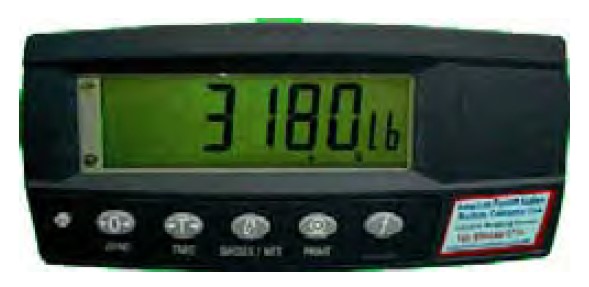
Activate Setup and Calibration Mode
FULL SETUP, (Codes), built
Hold down the small Power and f/OK buttons together for about three (3) Seconds to enter SetUp/Calibrate Mode. The indicator will display FULL SETUP, then build. The unit is now ready to adjust Setup parameters.

Calibration Procedure
General comment:
Your SEKO Weighing System can provide 99.9% or better accuracy and repeatability for most of your onboard weighing activities.
CALIBRATION
The Calibration process is performed in three steps:
- The first step establishes ZERO – the unloaded forks. We are weighing the empty forks to establish the ZERO (0) weight display.
- The second step records a known weight, called the SPAN weight.
- All subsequent weights are calculated using the ZERO and SPAN as reference points upon a linear vector.
Preliminary Tasks
Secure a known weight test load. We recommend a weight of at least half of the maximum machine-safe lifting capacity or use the maximum weight of your normal operation. Heavier is better than lighter.
Activate Calibration Mode
Simultaneously hold down the small Power Key and “f/OK” for two to four seconds to enter Set Up/Calibrate Mode and release the buttons when the display shows FULL SETUP. The indicator will display in automatic sequential order: FULL, SETUP, the firmware I.D., and bUiLD (BUILD)
The unit is now ready to calibrate ZERO.
- Press “0” (ZERO) until “CAL” (CAL) is displayed
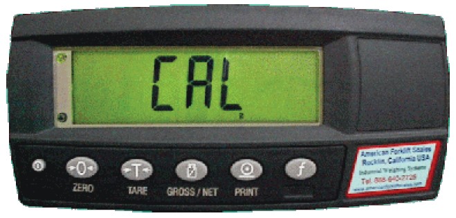
- Press “T” (Tare) to select “ZErO” (ZERO)

- Press the SELECT key and the display will show “(some flashing number)”.

Lift the empty forks to the weighing point and press “f/OK” to store the “ZErO”, (ZERO) setting.

The Display will show “Z.in.P” momentarily, then display “0 lb”.
- Press “T” (Tare)
- Press SELECT (two times) to select the “SPAN” (SPAN) key and the display will show “CLr.L N”
- Press PRINT to change N to y
- Press to store the “CLr.L N” setting. The Display will show a flashing “0 lb”
- Press The Display will show a flashing “X lb”
Enter your test weight value using the SELECT key to select the flashing digit and change the value of that flashing number with the PRINT key.

Lift the test weight and stop at the height where you will normally weigh your loads.
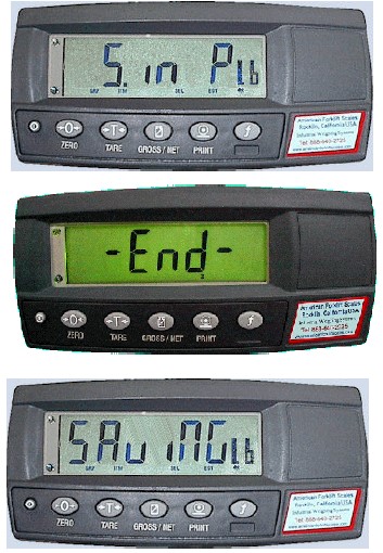
- Press “f/OK” to store the “SPAN” (SPAN) setting. The Display will show “S.in.P” momentarily, then display a flashing weight.
- Press “T” (Tare)
- Press “0” (ZERO) several times until “End” (END) is displayed
- Press “T” (Tare) to SAVE and Exit.
- The display will show “SAvinG” and enter normal Weighing Mode.
Testing for Repeatability and Adjusting for Accuracy
It is good practice to lift your test weight several times to determine the repeatability of the machine, Scale Set Up, and Driver Operation. If convenient, lift two or three other known weights of different ranges to assure yourself that the Weighing System weighs consistently and accurately across a range of weights. When your machine operation provides consistent results, you can shift the center of the weight display to bring the reading to the accurate weight of the test weight by the following process:
- Enter the Calibration mode
- Press ZERO button to go to CAL.
- Press TARE button two times to go to SPAN.
- Press the SELECT button two (2) times to enter the new SPAN calibration weight. The display will show the previous SPAN calibration weight.
- Use the SELECT and PRINT buttons to enter an adjusted SPAN calibration weight. If the scale reads high, then decrease the
- SPAN calibration weight by approximately 1/2 (50%) of the error, Lift the Test Weight and Press the “f/OK” button to store the new SPAN calibration weight.
- Press ZERO button several times to go to END, then press the TARE button to save the new settings.
- Repeat the tests for repeatability and accuracy and re-adjust the SPAN calibration weight until you are satisfied with the accuracy.
Call Tech Support if you need assistance. (307-321-4505)
FAQS About Rinstrum R320 Digital Truck Scale
What does Rinstrum x320’s zero error mean?
(ZERO) (ERROR) The weight reading exceeds the threshold established for operation at zero.
How is a zero inaccuracy corrected?
As the measured length is longer than the real length, you must deduct the zero error from the measured length in order to determine the actual length.
The primary zero mistake is what?
Positive zero mistake occurs when the main scale and a number greater than zero on the Vernier scale coincide.
What occurs when a sensor is not properly calibrated?
As a result, the sensor may not align properly or perform poorly.
What is the magnetic sensor’s accuracy?
Usually, the values are (0.04 and 0.005 mT).
What are the magnetic sensors’ sensitivities?
TMR ratio/2Hk is the formula used to determine a sensor’s sensitivity.
Calibration adjustment: what is it?
Usually, a calibration is followed by an adjustment.
How is calibration correction calculated?
The calibration correction is the difference between the value the instrument displayed during calibration and the standard’s certified value.
How is wavelength calibration done?
By measuring a spectrum with known wavelengths and scanning through the grating angles, the instrument’s wavelength calibration is carried out.
Why does zero error occur?
Equipment that is malfunctioning and doesn’t correctly reset to zero is what causes zero faults.
For more manuals by Rinstrum, Visit Manualsdock


