
Pioneer DMH-WT3800NEX Digital Multimedia Receiver
About Pioneer
Pioneer Corporation, sometimes known simply as Pioneer, is a worldwide company with headquarters in Tokyo that focuses on creating digital entertainment goods. Nozomu Matsumoto established the business on January 1st, 1938 in Tokyo as a radio and speaker repair shop. Shiro Yahara is the country’s current leader.
Precaution
information to user
- This device contains license-exempt transmitter(s)/receiver(s) that comply with Part 15 of FCC Rules and Innovation, Science, and Economic Development Canada license-exempt RSS(s). Operation is subject to the following two conditions:
- this device may not cause interference, and
- this device must accept any interference, including interference that may cause undesired operation of this device.
- This equipment complies with FCC/ISED radiation exposure limits for an uncontrolled environment and meets the FCC radio frequency (RF) Exposure Guidelines and RSS-102 of the ISED radio frequency (RF) Exposure rules. This equipment should be installed and operated keeping the radiator at least 20 cm or more away from the person’s body.
- This transmitter must not be co-located or operated in conjunction with any other antenna or transmitter. -Information to User
- Alteration or modifications carried out without appropriate authorization may invalidate the user’s right to operate the equipment.
- NOTE: This equipment has been tested and found to comply with the limits for a Class B digital device, under Part 15 of the FCC Rules. These limits are designed to provide reasonable protection against harmful interference in a residential installation. This equipment generates, uses, and can radiate radio frequency energy and, if not installed and used by the instructions, may cause harmful interference to radio communications. However, there is no guarantee that interference will not occur in a particular installation. If this equipment does cause harmful interference to radio or television reception, which can be determined by turning the equipment off and on, the user is encouraged to try to correct the interference by one or more of the following measures:
- Reorient or relocate the receiving antenna.
- Increase the separation between the equipment and the receiver.
- Connect the equipment to an outlet on a circuit different from that to which the receiver is connected.
- Consult the dealer or an experienced radio/TV technician for help.
- FEDERAL COMMUNICATIONS COMMISSION SUPPLIER’S DECLARATION OF CONFORMITY
- Product Name: RDS AV RECEIVER
- Model Number:
- DMH-WT3800NEX,
- DMH-WT38NEX
- Responsible Party Name: PIONEER ELECTRONICS (USA) INC. SERVICE SUPPORT DIVISION
- Address: 2050 W. 190TH STREET, SUITE 100, TORRANCE, CA 90504, U.S.A.
- Phone: 800-421-1404
- URl:httns://www.nioneerelectronics.com
WARNING
The Safety of Your Ears in Your Hands can be loud and harmful to your hearing. Guard against this by setting your equipment at a safe level BEFORE your hearing adapts.
- ESTABLISH A SAFE LEVEL:
- Siomy includes the soul until you can hear it comfortably and clearly, without distortion.
- Once you have established a comfortable sound level, set the dial and leave it there.
- BE SURE TO OBSERVE THE FOLLOWING GUIDELINES:
- – Do not turn up the volume so high that you can’t hear what’s around you.
- – Do note Hennessy le peating a moored alyaz theusertuations. headphones may create a traffic hazard and are illegal in many areas.
Getting started
Meanings of symbols used in this manual
This manual uses the following symbols to describe the touch screen operations.
- Touch
- Touch and hold
- Swipe
What’s What
Starting up the unit
- your language
- IStandard Mode] or [Network Mode] > [OK]
|WARNING Do not use the unit in Standard Mode when a speaker system for-way Network Mode is connected to the unit. This may cause damage to the speakers - [OK]
Wi-Fi® connection
- ” Screen
- 260→ → [Hotspot setting] → O, → [Select Wi-Fil → [Hotspot] → [Wi-Fi Settings: Hotspot]
Bluetooth® connection
- screen
- [Connection] ‘
NOTE The Bluetooth ® word mark and logos are registered trademarks owned by Bluetooth SIG, Inc. and any use of such marks by Pioneer Corporation is under license. Other trademarks and trade names are those of their respective owners.
CarAVAssist
Using CarAVAssist anytime, anywhere, optimize and expand your in-car and daily life.
[NOTE CarAVAssist must be connected to this unit to synchronize the changes.
Selecting the source/application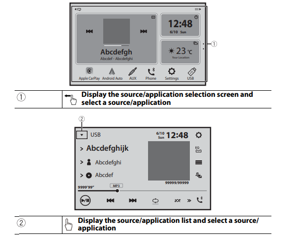
Tuner operation
- screen
- [Radio]

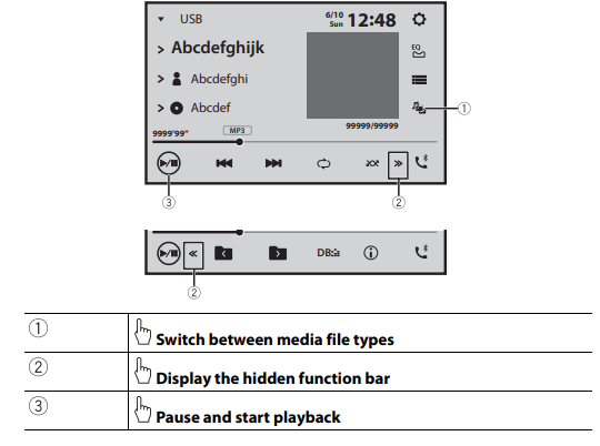
Audio operation
- screen
- USB
- → [Music]
Video operation
- screen
- IUSB]
- → [Video]

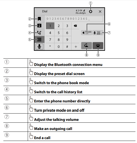
Bluetooth telephone operation
- screen
Important safety information
WARNING Rear visibility systems (backup cameras) are required in certain new vehicles sold in the U.S. and Canada. U.S. regulations began according to a two-year phase-in on May 1, 2016, and both the U.S. and Canada require that all such vehicles manufactured on or after May 1, 2018, have rear visibility systems. Owners of vehicles equipped with compliant rear visibility systems should not install or use this product in a way that alters or disables that system’s compliance with applicable regulations. If you are unsure whether your vehicle has a rear visibility system subject to U.S. or Canadian regulations, please contact the vehicle manufacturer or dealer.
If your vehicle has a compliant backup camera that displays the backup view through the factory receiver, do not use the Pioneer receiver unless it is connected to and displays the same view as the factory backup camera. Connection to the factory backup camera will require an adaptor, sold separately. Not all vehicles may be able to connect. Please check with a qualified professional installer for installation options specific to your vehicle.
Checking supplied items
- This product/ connection cables/ installation parts
- This product (×1)
- Power cord (×1)
- Pre-out cord (×1)
- USB cable (x1)
- LCD screen mounting bracket (×1)
- Spacer (×1)
- Front bracket (×1)
- Screws (nominal diameter x length, color)
- Flush surface screw (5 mm x 8 mm, Silver) (Хб)
- Binding head screw (5 mm x 8 mm, Silver) (x6)
- Binding head screw with adhesive (4 mm × 30 mm, Silver) (×4)
- Binding head screw with adhesive (4 mm × 12 mm, Silver) (×4)
- Binding head screw (4 mm x 5 mm, Black) (×4)
- Machine screw (2 mm x 4 mm, Black) (×4)
- GPS antenna/ installation parts
- GPS antenna (×1)
- Metal sheet (×1)
- Double-sided tape (×1)
- Clamps (×3)
- Microphone/ installation parts
- Microphone (×1)
- Double-sided tape (×1)
- Other items
- Manual(s) (×1)
- Warranty Card (×1)
| Connection
Precautions
Your new product and this manual
- Do not operate this product, any applications, or the rearview camera option (if purchased) if doing so will divert your attention in any way from the safe operation of your vehicle. Always observe safe driving rules and follow all existing traffic regulations. If you experience difficulty in operating this product, pull over, park your vehicle in a safe location, and apply the parking brake before making the necessary adjustments.
- Do not install this product where it may
- (i) obstruct the driver’s vision,
- (ii) impair the performance of any of the vehicle’s operating systems of safety features, including airbags, hazard lamp buttons, or
- (ili) impair the driver’s ability to safely operate the vehicle. In some cases, it may not be possible to install this product because of the vehicle type or the shape of the vehicle interior.
Important safeguards
WARNING Pioneer does not recommend that you install this product yourself. This product is designed for professional installation only. We recommend that only authorized Pioneer service personnel, who have special training and experience in mobile electronics, set up and install this product. NEVER SERVICE THIS PRODUCT YOURSELF. Installing or servicing this product and its connecting cables may expose you to the risk of electric shock or other hazards, and can cause damage to this product that is not covered by warranty.
Precautions before connecting the system
CAUTION
- Secure all wiring with cable clamps or electrical tape. Do not allow any bare wiring to remain exposed.
- Do not directly connect the yellow lead of this product to the vehicle battery. If the lead is directly connected to the battery, engine vibration may eventually cause the insulation to fail at the point where the wire passes from the passenger compartment into the engine compartment. If the yellow lead’s insulation tears as a result of contact with metal parts, short-circuiting can occur, resulting in considerable danger.
- It is extremely dangerous to allow cables to become wound around the steering column or shift lever. Be sure to install this product, its cables, and wiring away in such so that they will not obstruct or hinder driving.
- Make sure that the cables and wires will not interfere with or become caught in any of the vehicle’s moving parts, especially the steering wheel, shift lever, parking brake, sliding seat tracks, doors, or any of the vehicle’s controls.
- Do not route wires where they will be exposed to high temperatures. If the insulation heats up, wires may become damaged, resulting in a short circuit or malfunction and permanent damage to the product.
- Do not shorten any leads. If you do, the protection circuit (fuse holder, fuse resistor filter, etc.) may fail to work properly.
- Never feed power to other electronic products by cutting the insulation of the power supply lead of this product and tapping into the lead. The current capacity of the lead will be exceeded, causing overheating.
Before installing this product
- Use this unit with a 12-volt battery and negative grounding only. Failure to do so may result in a fire or malfunction.
- To avoid shorts in the electrical system, be sure to disconnect the (-) battery cable before installation.
To prevent damage
WARNING
- When speaker output is used by 4 channels, use speakers over 50 W (Maximum input power) and between 4 0 to 8 02 (impedance value). Do not use 1 0 to 3 1 speakers for this unit.
- When rear speaker output is used by 2 02 of the subwoofer, use speakers over 70 W (Maximum input power). *Please refer to connection for a connection method.
- The black lead is ground. When installing this unit or power amp (sold separately), make sure to connect the ground wire first. Ensure that the ground wire is properly connected to the metal parts of the car’s body. The ground wire of the power amp and the one of this unit or any other device must be connected to the car separately with different screws. If the screw for the ground wire loosens or falls out, it could result in fire generation of smoke or malfunction.

- Not supplied for this unit
- When replacing the fuse, be sure to only use a fuse of the rating prescribed on this product.
- When disconnecting a connector, pull the connector itself. Please do not pull the lead, as you may pull it out of the connector.
- This product cannot be installed in a vehicle without the ACC (accessory) position on the ignition switch. Consult with your nearest dealer if your vehicle is keyless.

- To avoid short-circuiting, cover the disconnected lead with insulating tape. It is especially important to insulate all unused speaker leads, which if left uncovered may cause a short circuit.
- For connecting a power amp or other devices to this product, refer to the manual for the product to be connected.
- The graphical symbol — placed on the product means direct current.
Notice for the blue/ white lead
- When the ignition switch is turned on (ACC ON), a control signal is output through the blue/white lead. Connect to an external power amp’s system remote control terminal, the auto-antenna relay control terminal, or the antenna booster power control terminal (max. 300 mA 12 V DC). The control signal is output through the blue/white lead, even if the audio source is switched off.
- Important When this product is in [Power OFF] mode, the control signal is also turned off. If (Power OFF] mode is canceled, the control signal is output again and the antenna is extended with the auto antenna function (if the antenna is being used). Be careful so that the extended antenna does not come into contact with any obstacles.
Rear panel (main terminals)
- This product
- GPS antenna 3.55 m (11 ft. 8 in.)
- iDatalink® or Metra adaptor inputRefer to the instruction manual for the iDatalink or Metra adaptor (sold separately).
- USB port
- Microphone 3 m (9 ft. 10-1/8 in.)
- Antenna jack I
- Pre-out supply
- Power supply
- Fuse (10A)
- Wired remote input Hard-wired remote control adaptor can be connected (sold separately).
- SiriusXM® Connect Vehicle Tuner Refer to the instruction manual for SiriusXM Connect Vehicle Tuner (sold separately).
_NOTES
- Before using and/or connecting the iDatalink Maestro® adaptor (sold separately), you will need to first flash the Maestro module with the appropriate vehicle and head unit firmware. You can find the device number that is required for the activation on the following (refer to the Operation Manual.):
- – The label on the packaging of this product
- – The label on this product
- – The [Firmware Information] screen
- When the iDatalink Maestro adaptor is connected, use the microphone of this unit to perform voice operations for Apple CarPlay or Android Auto’™.
- SiriusXM and all related marks and logos are trademarks of Sirius XM Radio, Inc. All rights reserved.
- Android Auto is a trademark of Google LLC.
- Apple CarPlay is a trademark of Apple Inc.
- iDatalink, Maestro, and iData are registered trademarks of Automotive Data Solutions Inc.
Power cord
WARNING IMPROPER CONNECTION MAY RESULT IN SERIOUS DAMAGE OR INJURY INCLUDING ELECTRICAL SHOCK, AND INTERFERENCE WITH THE OPERATION OF THE VEHICLE’S ANTILOCK BRAKING SYSTEM, AUTOMATIC TRANSMISSION, AND SPEEDOMETER INDICATION.
- To power supply
- Power cord
- Yellow To terminal supplied with power regardless of ignition switch position.
- Red To electric terminal controlled by ignition switch (12 V DC) ON/OFF
- Orange/white To lighting switch terminal.
- Black (ground) To vehicle (metal) body.
- Violet/white Of the two lead wires connected to the back lamp, connect the one in which the voltage changes when the gear shift is in the REVERSE (R) position. This connection enables the unit to sense whether the car is moving forward or backward.
- Pink Car speed signal input
- Blue/white Connect to the system control terminal of the power amp (max. 300 mA 12 V DC).
- Light green is Used to detect the ON/OFF status of the parking brake. This lead must be connected to the power supply side of the parking brake switch. If this connection is made incorrectly or omitted, certain functions of this product will be unusable.
Speaker leads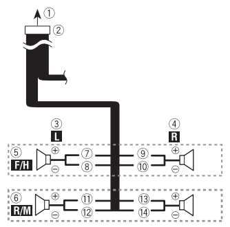
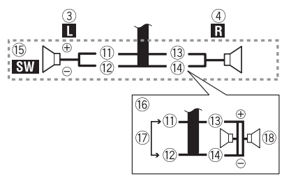
- To power supply
- Power cord
- Left
- Right
- Front speaker (STD) or high-range speaker (NW)
- Rear speaker (STD) or middle range speaker (NW)
- White
- White/Black
- Gray
- Gray/black
- Green
- Green/black
- Violet
- Violet/black
- Subwoofer (4 Q)
- When using a subwoofer of 2 12, be sure to connect the subwoofer to the violet and violet/black leads of this unit. Do not connect anything to the green and green/black leads.
- D Not used.
- Subwoofer (4 0) × 2
NOTES
- When a subwoofer is connected to this product instead of a rear speaker, change the rear output setting in the initial setting. The subwoofer output of this product is monaural. For details, refer to the Operation Manual.
- With a two-speaker system, do not connect anything to the speaker leads that are not connected to speakers.
Power amp (sold separately)
Important
The speaker leads are not used when this connection is in use.
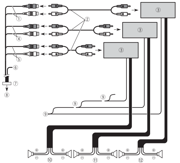
- ( Subwoofer output (SUBWOOFER OUTPUT) 23 cm (9 in.) (STD) Low range output (NW)
- RCA cable (sold separately)
- Power amp
- Front output (FRONT OUTPUT) 15 cm (5-7/8 in.) (STD) High range output (NW)
- Rear output (REAR OUTPUT) 15 cm (5-7/8 in.) (STD) Middle range output (NW)
- Yellow/black (MUTE) If you use an equipment with a Mute function, wire this lead to the Audio Mute lead on that equipment. If not, keep the Audio Mute lead free of any connections.
- Pre-out cord
- To pre-the supply
- System remote control Connect to Blue/white cable (max. 300 mA 12 V DC).
- Rear speaker (STD) Middle range speaker (NW
- Front speaker (STD) High range speaker (NW)
- Subwoofer (STD) Low range speaker (NW)
iPhone and smartphone
NOTES
- For details on how to connect an external device using a separately sold cable, refer to the manual for the cable.
- iPhone and Lightning are trademarks of Apple Inc., registered in the U.S. and other countries.
iPhone
Connecting via the USB port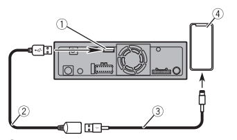
- O USB port
- USB cable 1.5 m (4 ft. 11 in.)
- USB interface cable for iPhone (sold separately)
- iPhone with Lightning connector Smartphone (Android™ device)
Smartphone (Android™ device)
NOTE For details concerning the connection and operations of the smartphone, refer to the Operation Manual.
Connecting via the USB port
- D USB port
- USB cable 1.5 m (4 ft. 11 in.)
- USB – micro USB cable (USB Type-A to micro USB Type-B) (sold separately) USB Type-C® cable (USB Type-A to USB Type-C) (sold separately)
- Smartphone
Camera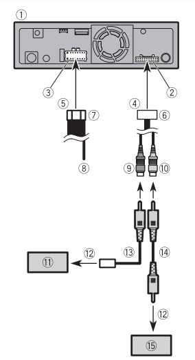
- © This product
- Pre-out supply
- Power supply
- To pre-the supply
- To power supply
- Pre-out cord
- Power cord
- Violet/white (REVERSE-GEAR SIGNAL INPUT)
- Brown (REAR VIEW CAMERA IN) 23 cm (9 in.)
- Yellow* (SECOND CAMERA INPUT) 23 cm (9 in.)
NOTE I Do not use the second camera for any purpose other than driving assistance and iDatalink. - Rearview camera (ND-BC8) (sold separately)
- To video output
- RCA power supply cable (supplied with ND-BC8)
- RCA cable (sold separately)
- View camera (sold separately)
Not available for DMH-WT38NEX
NOTES
- Connect only the rearview camera to the brown cable. Do not connect any other equipment.
- Some appropriate settings are required to use rear-view cameras. For details, refer to the Operation Manual.
External video component
Using an AUX input
- This product
- Pre-out supply
- To pre-the supply
- Pre-out cord
- AUX input (AUX IN) 15 cm (5-7/8 in.)
- Mini-jack AV cable (sold separately)
- Yellow
- Red, white
- RCA cables (sold separately)
- To video output
- To audio output
- External video component (sold separately)
Rear display
(Only for DMH-WT3800NEX)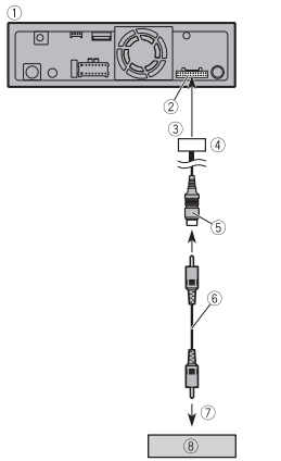
- This product
- Pre-out supply
- To pre-the supply
- Pre-out cord
- Yellow* (REAR MONITOR OUTPUT) 30 cm (11-7/8 in.)
- RCA cable (sold separately)
- To Video input
- Rear display with RCA input (sold separately) * Not available for DMH-WT38NEX
Installation
Precautions before installation
CAUTION
- Never install this product in places where, or in a manner that:
- -Could injure the driver or passengers if the vehicle stops suddenly.
- – May interfere with the driver’s operation of the vehicle, such as on the floor in front of the driver’s seat, or close to the steering wheel or shift lever.
- To ensure proper installation, be sure to use the supplied parts in the manner specified. If any parts are not supplied with this product.use compatible parts in this product, use compatible parts in the manner specified after you have the part compatibility checked by your dealer.
- parts other than supplied or compatible ones are used, they may damage internal parts of this product or they may work loose and the product may become detached. I
- t is extremely dangerous to allow cables to become wound around the steering column or shift lever. Be sure to install this product, its cables, and wiring away in such so that they will not obstruct or hinder driving. Make sure that leads cannot get caught in a door or the sliding mechanism of a seat, resulting in a short circuit. Please confirm the proper function of your vehicle’s other equipment after the installation of this product.
- Do not install this product where it may (1) obstruct the driver’s vision, (ii) impair the performance of any of the vehicle’s operating systems or safety
Before installing
- Consult with your nearest dealer if installation requires drilling holes or other modifications of the vehicle.
- Before making a final installation of this product, temporarily connect the wiring to confirm that the connections are correct and the system works properly.
Installation notes
- Do not install this product in places subject to high temperatures or humidity, such as:
- – Places close to a heater, vent, or air conditioner.
- – Places exposed to direct sunlight, such as on top of the dashboard.
- – Places that may be exposed to rain, such as close to the door or on the vehicle’s floor
Installation using the screw holes on the side of this product
Read the following chapters to choose from two types of installation methods (floating style or modular style). • Floating style installation (page 16)
- Modular style installation (page 17)
- Floating style installation
- Installation tips The following procedure describes installing this product with an LCD screen attached to the unit. Depending on the vehicle or installation location, you may need to adjust the mounting position of the LCD screen to prevent For artist routine stations dimensions, refer to The adjusting position
- Fasten this product to the factory radio-mounting bracket. Position this product so that its screw holes are aligned with the screw holes of the bracket, and tighten the screws at three locations on each side.
- Factory radio-mounting bracket
- If the pawl interferes with installation, you may bend it down out of the way.
- Dashboard or console
- Binding head screw (5 mm x 8 mm) / Flush surface screw (5 mm x 8 mm) Be sure to use the screws supplied with this product.

- Facethe coman unpunishable Depending on the vehicle, the front-back position of the LCD screen may sue to pour out lente front position install the LCD screen.

- LCD screen mounting bracket
- Binding head screw (4 mm x 30 mm)
- Spacer

- Detach the monitor cover from the LCD screen (e), then connect the monitor cables to the LCD screen (6). After that, attach the LCD screen by adjusting the up-down position (G) to this unit by using the screws on each side (0). Push the monitor cables as far as possible in this product before attaching the ICD screen.

- Monitor cover
- Binding head screw (4 mm x 12 mm)
- Secure the monitor cables to the hook on the back of the LCD screen then attach the monitor cover (0) by using the screws (0).
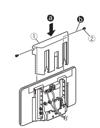
- Factory radio-mounting bracket
- If the pawl interferes with installation, you may bend it down out of the way.
- Dashboard or console
- Binding head screw (5 mm x 8 mm) / Flush surface screw (5 mm x 8 mm) Be sure to use the screws supplied with this product.
- Fasten this product to the factory radio-mounting bracket. Position this product so that its screw holes are aligned with the screw holes of the bracket, and tighten the screws at three locations on each side.
- Installation tips The following procedure describes installing this product with an LCD screen attached to the unit. Depending on the vehicle or installation location, you may need to adjust the mounting position of the LCD screen to prevent For artist routine stations dimensions, refer to The adjusting position
Installing the GPS antenna
CAUTION Do not cut the GPS antenna lead to shorten it or use an extension to make it longer. Altering the antenna cable could result in a short circuit or malfunction and permanent damage to this product.
Installation notes
- The antenna should be installed on a level surface where radio waves will be blocked as little as possible. Radio waves cannot be received by the antenna if reception from the satellite is blocked.
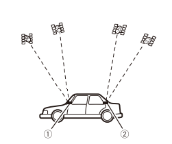
-
- Dashboard
- Rear shelf
- When installing the GPS antenna inside the vehicle, be sure to use the metal sheet provided with your system. If this is not used, the reception sensitivity will be poor.
- Do not cut the accessory metal sheet. This would reduce the sensitivity of the GPS antenna.
- Take care not to pull the antenna lead when removing the GPS antenna. The lead may become detached.
- Do not paint the GPS antenna, as this may affect its performance.
When installing the antenna inside the vehicle (on the dashboard or rear shelf)
WARNING
Do not install the GPS antenna over any sensors or vents on the dashboard of the vehicle, as doing so may interfere with the proper functioning of such sensors or vents and may compromise the ability of the metal sheet under the GPS antenna to properly and securely affix to the dashboard.
- GPS antenna
- Metal sheet Peel off the protective sheet on the rear.
- Double-sided tape
- Clamps Use clamps to secure the lead where necessary inside the vehicle.
NOTES
- Affix the metal sheet on the surface as level as possible where the GPS antenna faces the window.
- Affix the GPS antenna on the metal sheet using the double-sided tape.
- The metal sheet contains a strong adhesive which may leave a mark on the surface if it is removed.
- When attaching the metal sheet, do not cut it into small pieces.
- Some models use window glass that does not allow signals from GPS satellites to pass through. On such models, install the GPS antenna on the outside of the vehicle.
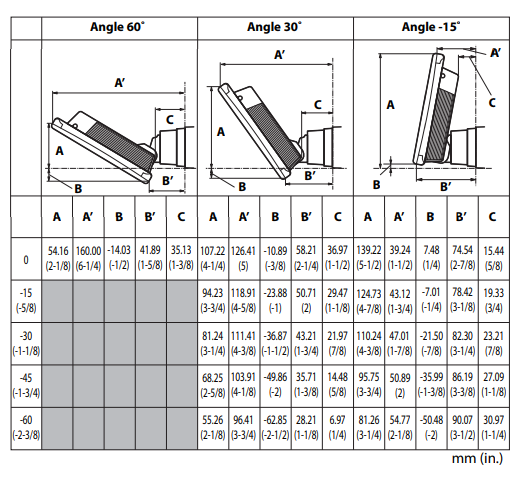
The adjusting position and the mounting dimension of the display for floating-style installation
The mounting position of this unit’s display can be adjusted (front-back/up-down/ right-left/angle). When mounting the display, adjust the mounting position and dimensions so that your view is clear and it does not impair your driving.
WARNING
Make sure that none of the following conditions exist when mounting the display. Otherwise, an accident may occur.
- It impairs the operation of the steering wheel and levers (shift lever, windshield wiper switch, turn signal switch, etc.).
- It impairs the operation of the airbags.
- It significantly impairs the operation of the hazard switch.
- It impairs the ability to identify or operate other control switches.
- You are unable to see gauges, meters, or warning indicators.
- It interferes with in-vehicle devices (switches panel glove compartment
Display mounting dimensions and adjustable positions
Front-back position
Left-right position
Adjustable display angles and up-down positions
WARNING especially can users hand so during adjusting the LCD screen angle. 
Mounting dimension with the angle range of the display
Front angle range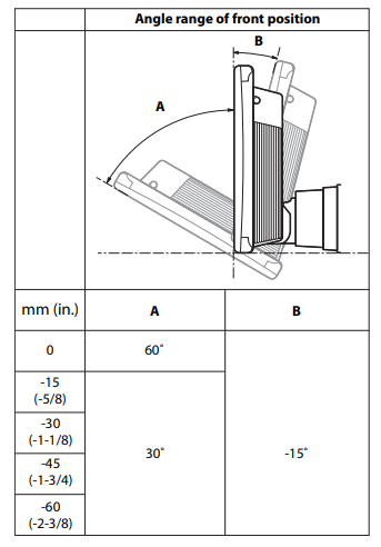
Back angle range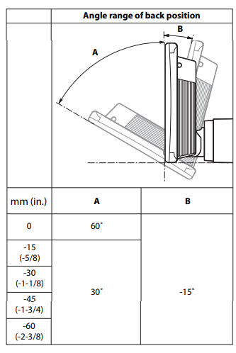
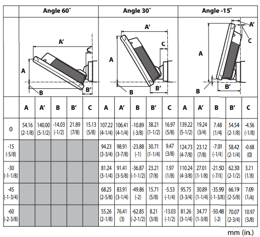
[NOTES
- adjusted are neid that in the trad dimensiodicates that the display can not be
- The displayed angle range is the movable range of this unit, and it may vary depending on the vehicle in which the unit is installed.
The adjusting position of the display for modular-style installation
The mounting up-down position of this unit’s display can be adjusted. When mounting the display, adjust the mounting position so that your view is clear and it does not impair your driving.
Register your product at
- PIONEER CORPORATION
28-8, Honkomagome 2-chrome, Bunkyo-ku, Tokyo 113-0021, Japan - PIONEER ELECTRONICS (USA) INC.
- P.O. Box 1540, Long Beach, CA 90801-1540, U.S.A.
- TEL: (800) 421-1404
- PIONEER EUROPE NV
- Haven 1087, Keetberglaan 1, B-9120 Melsele, Belgium/Belgique
- TEL: (0) 3/570.05.11
- PIONEER ELECTRONICS ASIACENTRE PTE. LTD.
- No. 2 Jalan Kilang Barat, #04-02, Singapore 159346
- TEL: 65-6378-7888
- PIONEER ELECTRONICS AUSTRALIA PTY. LTD.
- Unit 13, 153-155 Rooks Road, Vermont, Victoria, 3133 Australia
- TEL: (03) 9586-63003
FAQs about Pioneer DMH-WT3800NEX Digital Multimedia Receiver
Are Pioneer receivers Bluetooth compatible?
surprisingly good because to Pioneer’s Sound Retriever AIR technology, which returns lost audio quality during Bluetooth transfer and is available on all Pioneer AV receivers equipped with Bluetooth. Compromise used to be necessary for portable music and a robust home entertainment system.
Does Android Auto support Pioneer?
Pioneer’s flagship receivers for 2021 support both Apple CarPlay (Wire & Wireless) and Android Auto, and they come equipped with built-in Amazon Alexa.
Does Pioneer have a mobile app?
Examine pictures saved on your AndroidTM or iPhone® device. You may see a slideshow and access albums and camera rolls. Included with the Pioneer AppRadioTM app is functionality.
Which app is compatible with the Pioneer radio?
You can make better use of the features on your smartphone with Pioneer Smart Sync. Your smartphone and a compatible Pioneer vehicle radio are connected.
Does Pioneer support CarPlay?
With its incredible array of music sources, hands-free calling capabilities, music streaming, and plenty of sound sculpting options, the Pioneer DMH-1500NEX 7″ digital multimedia receiver is a great addition to any dashboard. Access to the most recent smartphone integration services is made possible by compatibility with both Apple CarPlay and Android Auto.
Does Pioneer have Android Auto that is wireless?
With the help of Wi-Fi wireless networking, this Pioneer receiver allows you to connect your smartphone to it without the need for a cable. It is also compatible with Apple CarPlay and Android Auto. Wired or wireless is up to you.
Is there a backup camera for Pioneer?
With 746 reviews, the Pioneer NTSC Universal Backup Camera Black ND-BC8 has a 4.5 out of 5 star user rating on Best Buy.
For more manuals by Pioneer, visit Manualsdock


