
Bilanciai B-TEK Scales T503W
About B-TEK
B-TEK is a company that specializes in the design, manufacturing, and distribution of weighing systems and equipment. They provide a wide range of industrial weighing solutions for various industries and applications. Some of their key product offerings and areas of expertise include:
- Weighing Scales: B-TEK manufactures a variety of weighing scales, including bench scales, floor scales, platform scales, and more. These scales are used for accurate weight measurement in industrial, commercial, and laboratory settings.
- Truck Scales: B-TEK produces truck scales and weighbridges for accurately measuring the weight of trucks and other heavy vehicles. These scales are commonly used in logistics, agriculture, waste management, and other industries.
- Custom Weighing Solutions: B-TEK offers custom weighing solutions to meet the unique needs of their customers. They can design and build specialized weighing systems for specific applications.
- Weighing Software: They provide software solutions for data management, process automation, and weight recording to enhance the efficiency and accuracy of weighing operations.
- Load Cells and Components: B-TEK manufactures load cells and other weighing components, which are essential for the accurate functioning of weighing equipment.
- Service and Support: B-TEK offers maintenance, repair, and calibration services to ensure the ongoing accuracy and reliability of their weighing systems.
- Various Industries: B-TEK serves a diverse range of industries, including agriculture, logistics, manufacturing, food processing, waste management, and more.
Introduction
This manual contains information on the installation, calibration, and setup of the instrument.
Approvals
- C-tick approved and CE approved.
Trade versions
- NSC approval (4000 divisions at 0.8μV/division).
- NMI approval (4000 divisions at 0.8μV/division).
- NTEP approval (10000 divisions at 0.8μV/division).
Manuals
For more information on this instrument refer to the Reference Manual visit www.B-TEK.com, Quick Start Manual, or Communications Manual.
Shipping Contents
The following table identifies the items shipped with the indicator. Please check that your packing box contains the specified items.

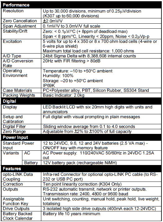
Specifications
Warnings
General
- Indicator not to be subject to shock, excessive vibration, or extremes of temperature (before or after installation).
- Inputs are protected against electrical interference, but excessive levels of electromagnetic radiation and RFI may affect the accuracy and stability.
- For full EMC or RFI immunity, termination of cable shields and correct earthing of the instrument is essential.
- Indicator and load cell cables are sensitive to excessive electrical noise. Install well away from any power or switching circuits.
Configuration Issues
- Configuration and calibration can be performed from the front panel, using digital setup. When Full Setup is used, all menu items are accessible and care must be taken to ensure no accidental changes are made to calibration and trade settings.
- Enter a passcode to prevent unauthorized or accidental tampering. If the passcode is lost, the manufacturer should be contacted for further advice.
Installation
The following steps are required to set up the indicator.
- Inspect the indicator to ensure good condition.
- Use connection diagrams to wire up load cell, power, and auxiliary cables as required.
- Connect Power to the indicator and press the <POWER> key to turn the instrument On.
- Refer to the Instrument Setup section on page 17 for information on configuring and calibrating the instrument.
- To turn the instrument Off press and hold the <POWER> key for three seconds (until the display blanks).
Electrical Safety
- For your protection, all main electrical hardware must be rated for environmental conditions of use.
- Pluggable equipment must be installed near an easily accessible power socket outlet.
- To avoid the possibility of electric shock or damage to the instrument, always switch off or isolate the instrument from the power supply before maintenance is carried out.
opto-LINK
The optional opto-LINK cable can be used to transfer setup and calibration information from a PC (eg. to be stored for later use and/or transferred to other instruments). It can also be used to download software upgrades to the instrument from a PC.
- Attach the opto-LINK cable to the PC using the DB9 or USB connector.
- Attach the opto-LINK head to the left side of the instrument display using the permanent magnet located within the head of the opto-LINK.

WARNING: The Opto-LINK head contains a strong magnet and care should be taken with its proximity to electronic media (e.g. credit cards, floppy disks, etc.) and/or other electronic instrumentation.
Connections
Cable Connections
- All cable connections are made to the rear of the instrument using pluggable screw terminals.

4-Wire Connection
The minimum connectivity requirements are the connection of four wires (i.e. Excitation + and – along with Signal + and –). The BUILD: CABLE option must be set to 4 to allow for a 4-wire connection.

6-Wire Connection
The excitation and signal lines are connected the same as for a 4-wire installation. The BUILD: CABLE option must be set to 6 (the default) to allow for a 6-wire connection.

Auxiliary Connections
This section provides diagrams to illustrate the terminal connections.
RS-232 Serial to PC
- Network: One Instrument to PC (DB9) (RXD, TXD, GND)

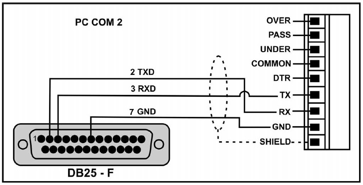
- Network: One Instrument to PC (DB25) (RXD, TXD, GND)
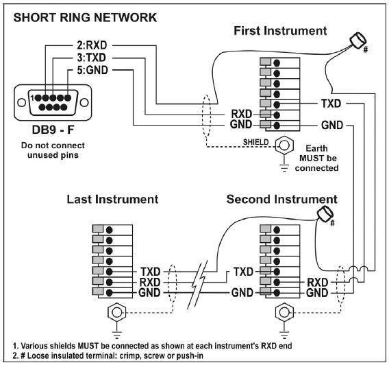
- Ring Networks: Multiple Instruments to PC (RXD, TXD, GND)
Instruments can be configured in a Ring Network. The Short Ring Network layout should only be used up to a total cable run length of about 150 m (500 ft) at 9600 baud in a clean EMC environment. If communications errors persist, or for longer cable runs, select lower baud rates and/or use the Long Ring Network below. For DB25 connector, see
- Network: One Instrument to PC (DB25) (RXD, TXD, GND) above.
In a Ring Network, the Instruments must have:
- same serial options, i.e., baud, parity, data bits, stop bits;
- unique addresses.
Short Ring Network
Long Ring Network
The Long Ring Network layout can be used where each leg of the cable run can be up to about 150 m (500 ft) at 9600 baud. If comms errors persist, lower the baud rate to 4800 or 2400. This section provides diagrams to illustrate the terminal connections.

Outputs
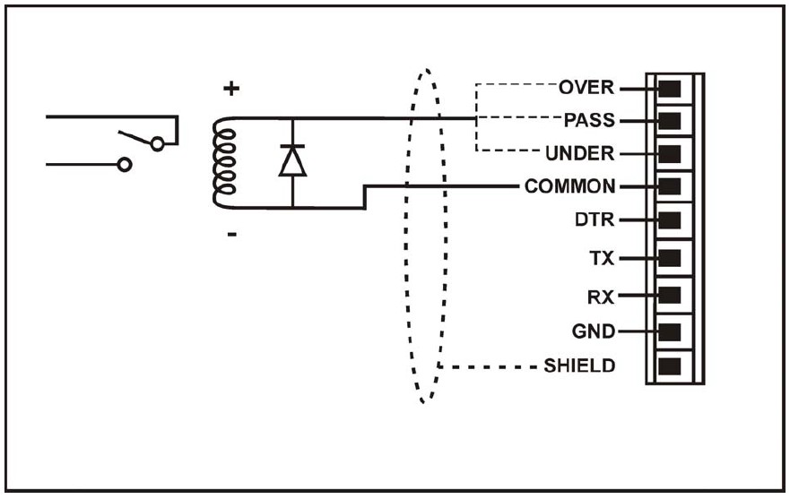
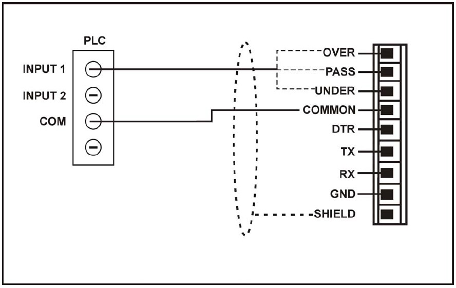
- The output drivers for the instrument are high-side drives and are capable of driving up to 400mA each.
- This configuration allows for the direct connection of the instrument outputs to most types of PLC.
- The voltage applied to the instrument’s positive power supply terminal (+) appears on the output lines when the outputs are active.
- To drive external loads (e.g. relays), connect the output line directly to the positive side of the relay coil. Connect the negative side of the relay coil to COMMON.
- It is recommended that fly-back diodes or transient suppressors be fitted across inductive loads such as relay coils to limit switching noise.
Outputs to Drive Relay
Outputs to Drive PLC
Cable Shield Connection and Earthing
- Care should be taken when connecting shields to maximize EMC or RFI immunity and minimize earth loops and crosstalk (interference) between instruments.
- For full EMC or RFI immunity, termination of the cable shields at the earth lug is very important. The earth lug of the instrument must be separately connected to ground potential via a reliable link.
- The instrument should only be connected to the earth via a single reliable link to avoid earth loops.
- Where each instrument is separately earthed, interconnecting cable shields should be connected at one end only. This also applies to Ring Networks.
- Caution: Some load cells connect the cable shield directly to the load cell (and therefore the scale base). The connection of the load cell cable shield in this situation may be site-specific.
Instrument Setup
Calibration Counter
The built-in calibration counter(s) monitor the number of times trade critical settings are altered. Refer to Trade Critical
Settings below for more information and to the OPTION: USE setting page.
The table below describes when the counter(s) will increment.
- Industrial, NSC, or OIML: The Calibration Counter increments when trading critical settings are changed. An example of the counter is C.00019.
- NTEP: Two counters display.
• The Calibration Counter increments when trade critical settings in the Calibration (CAL) menu are changed. An example of the counter is C.00010.
• The Configuration Counter increments when other trade critical settings (ie. not in the CAL menu) are changed. An example of the counter is F.00009.
Trade Critical Settings
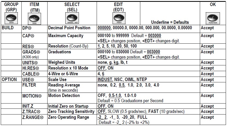
Trade critical settings can affect calibration and/or legal for trade performance. In this document, the ⊗ symbol indicates the setting is trade critical. Each time a trade critical setting is altered, the calibration counter will be incremented by one.
Access Full Setup
Full Setup provides access to configure and calibrate the instrument. All items in all menus will be enabled in Full Setup.
WARNING: Care should be taken to avoid inadvertently altering the Build or Calibration settings.
- Ensure the instrument is on.
- Press and hold the <POWER> and <GROSS/NET> keys together for two seconds.

Settings
The following tables identify the settings available for the instrument.
Error Messages
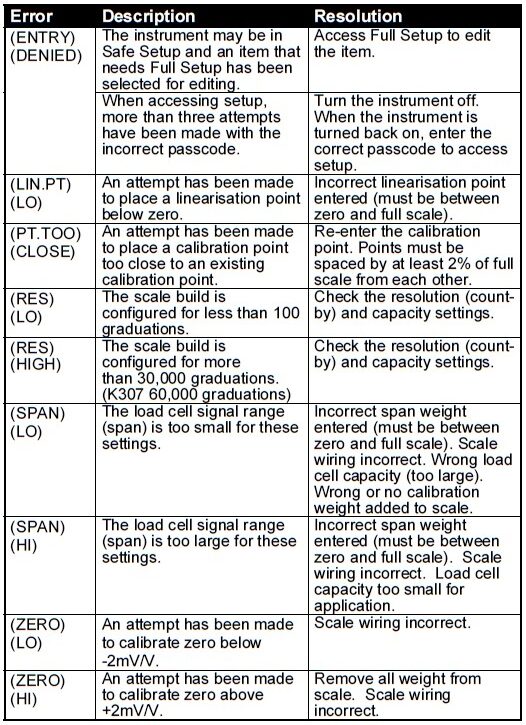
Setup and Calibration Errors
Diagnostic Errors
- Check: This item can be checked on-site by service personnel.
- Return for Service: The instrument must be returned to the manufacturer for factory service.

The E-type error messages are additive. For example, if the instrument is running off batteries and the temperature drops, the battery voltage may be too low. The resulting error message will be E0011 (0001 + 0010). The numbers are added in hexadecimal as follows:
1 – 2 – 3 – 4 – 5 – 6 – 7 – 8 – 9 – A – B – C – D – E – F (For example, 2 + 4 = 6, or 4 + 8 = C)
Visit Us
1510 Metric Ave SW Canton, OH 44706, USA
Tel: 330.71.8900
Fax: 330.471.8909
www.B-TEK.com
FAQS About Bilanciai B-TEK Scales T503W
What do scales primarily serve?
Scales offer defense against the elements and predators.
Do scales indicate weight or mass?
Weight is measured with scales.
Can scales display incorrect weight?
Scales expecting materials to rest uniformly on the load cells can give up false results if they are set up on a slope.
Do scales have different capacities?
From day to day, or even from moment to moment, they may give you a different weight.
What material are scales made of?
Collagen, dentin, keratin, and enamel.
Scales able to quantify fat?
They calculate how much of that weight is made up of water, body fat, and fat-free mass.
How does scale weight fluctuate?
eating, drinking, peeing, pooping, and working out
How much time do scales last?
five to ten years
What are the most accurate scales?
Body Comp Scales by Withings
What is the scale’s accuracy?
The degree to which the average value of an object’s displayed weight is near to the object’s actual weight is a measure of a scale’s accuracy.
For more manuals by B-TEK, Visit Manualsdock
[embeddoc url=”https://manualsdock.com/wp-content/uploads/2023/10/Bilanciai-B-TEK-Scales-T503W-Quick-Start-Manual.pdf” download=”all”]


