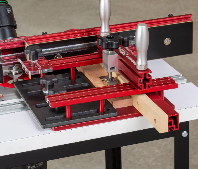
Woodpecker Iron Grip Coping Sled
About Woodpecker
AP-A Dental Air polisher uses compressed air to drive the prophylaxis powder and spray water together on the tooth surface to remove the attachments on the tooth surface (such as dental plaque, pigment, soft dirt, etc.),
INSTALLATION
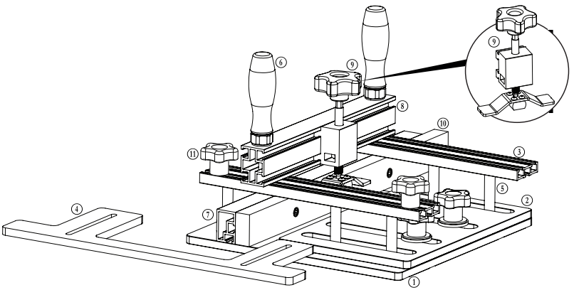
- (1) Base
- (1) Top Plate
- (2) Top Track
- (1) Acrylic Guide
- (6) Spacer Tube
- (2) Bridge Handle
- (1) Fence
- (1) Bridge
- (1) Spring Clamp
- (3) Spoil Board
- (4) Knob, 1/4-20
- (1) Ball Wrench 3/16″
- (1) Allen Wrench 5/32″
HARDWARE BAG A
- (6) Weldnut, 1/4-20
- (4) Flat Head Machine Screw. 1/4-20 x 2-3/4″
- (2) Button Head Screw, 1/4-20 x 2-1/2″
HARDWARE BAG B
- (2) Hex Head Bolt-A, 1/4 × 20 × 2-1/2″
- (2) Nylon Washer-A (black), 1/4 × 7/8″
- (2) Nylon Washer-A (black), 1/4 × 7/8″
- (2) Hex Head Bolt-B. 1/4-20 × 1″
- (2) Nylon Washer-R 1/4 y 3/4″
HARDWARE BAG C
- (2) Flat Head Machine Screw 1/4-20 x 1-1/2″,
- (2) Nylon Washer. 1/4 x 1-3/8″
- (2) Fender Washer, 1/4 x 1-1/4″
- (2) Kept Nut, 1/4-20
- (2) SAE Washer, #10
HARDWARE BAG D
- (8) Weldnut, 1/2-20
- (5) Flat Head Screw, 1/4-20 × 5/8
- (3) Cap Screw, 1/4-20 x 3/4″
ASSEMBLING
AT THIS POINT YOU WILL NEED:
- Base
- Fence
- Spoil Board (3)
- Steel Dowel Pin, 1/4 × 2″ (2)
- Allen Wrench 3/16″
- HARDWARE BAG D
- Weld nut, 1/2-20 (8)
- Flat Head Screw, 1/4-20 × 5/8″ (5)
- Cap Screw, 1/4-20 × 3/4″ (3)
- Insert the (5) Flat Head Machine Screws up through countersunk holes in the bottom of the Base then loosely thread on (5) Weldnuts. Do not tighten. FIGURE A.
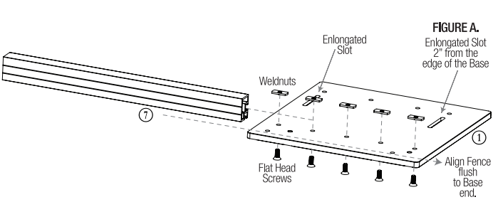
- Slide the Fence © onto the Weldnuts. Ensure that the 1-1/2″ tall face with the t-slot track is facing the elongated slots in the Base.
- Align the end of the Fence flush with the side of the Base where the elongated slot is located 2″ in from the edge. NOTE: This will be referred to as the “Front Edge” for the remainder of the instructions.
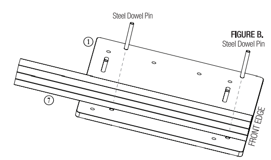
- Insert the (2) Steel Dowel Pins into the holes behind the Fence. Align the Fence flush with the front edge of the Base and pull it back against the Steel Dowel Pins. Firmly tighten the Flat Head Screws from underneath the Base. Once secured, remove the Steel Dowel Pins. FIGURE B.
- Insert (3) Cap Screws through the counter sunk holes in the Spoil Board 1. Loosely thread the (3) Weldnuts onto the Cap Screws. Slide the Spoil Board onto the fence by slotting the Weldnuts into the t-slot track of the Fence. FIGURE C.

- 6. Ensure that the Spoil Board is flush with the front edge of the Base. Secure it in place by tightening the Cap Screws with the Allen Wrench.
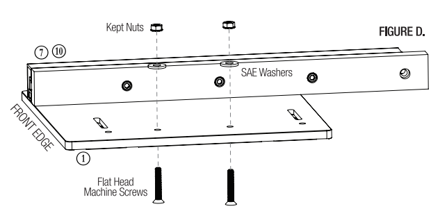
- Insert the (2) Flat Head Screws up through the bottom of the Base in the two center-spaced holes along the edge of the Base. Add the SAE Washers (gold color) and tightly thread on the Kept Nuts. FIGURE D.
- Insert the (2) Button Head Screws up through the bottom of the Base in the elongated slots. From the top add Spacer Tubes © and Weldnuts onto each Button Head Screw. Do not tighten. Leave approximately 1/8″ gap between the top of the Spacer Tube and the bottom of the Weldnut. FIGURE E.
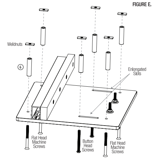
- Insert the (4) Flat Head Machine Screws up through the bottom of the Base in the four corner holes. From the top add Spacer Tubes © and Weldnuts onto each Flat Head Machine Screw. Do not tighten.
- Set the Top Plate 2 on top of the Base so that the two center screw threads pass through the two center slots on the Top Plate. The outside slots on the Top Plate should line up with the Spacer Tube Assemblies. FIGURE F.
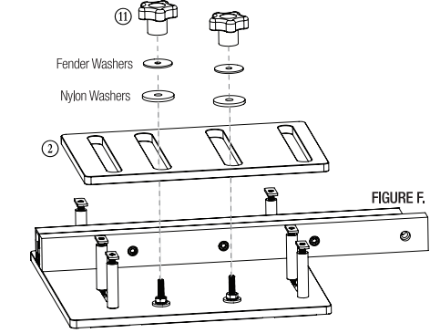
- Place a Nylon Washer on each of the center screw assemblies followed by a Fender Washer. Thread a Knob 10 onto each of the center screws to secure the Top Plate to the Base.
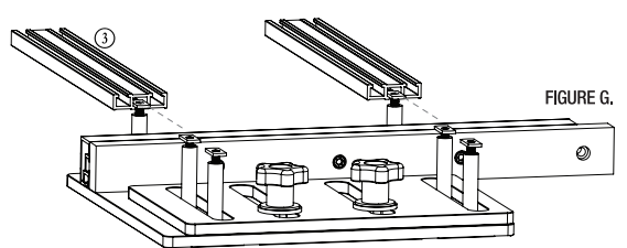
- Slide a Top Track onto the Spacer Tube Assemblies with the single-track side down, until all three Weldnuts are captured in the slot of the Top Track. The back end of the Top Track should be flush with the back edge of the Base.
- Firmly tighten both Flat Head Screws in the Spacer tube Assembly from underneath. Use the Allen Wrench to secure the center Button Head Screws.
- Repeat steps 12 and 13 for the second Top Track. FIGURE G.
- Slide the Hex Head Bolt-A into the outside slot of each Top Track. FIGURE H.
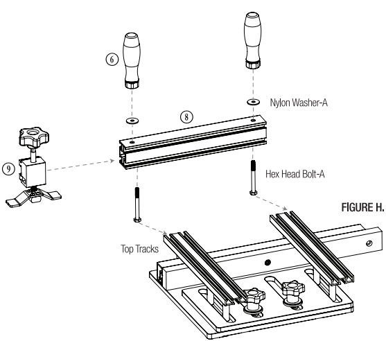
- Slide the Work Holding Clamp ® onto the T-slot track on the Bridge 8.
- Place the Bridge with the Work Holding Clamp installed so that the Hex Head Bolts-A pass through the pre-drilled holes in the Bridge. NOTE: Ensure that the Work Holding Clamp is on the same side of the Fence as the Spoil Board.
- Add a Nylon Washer-A to each Hex Head Bolt-A and then thread on the two Bridge Handles © to lock the Bridge in place.
- On each end, slide the Hex Bolts head into the outside slot on the front Top Track. Set the Acrylic Guide ® in place so that the two Hex Head Bolts-B protrude up through the slots of the Acrylic Guide. FIGURE I.
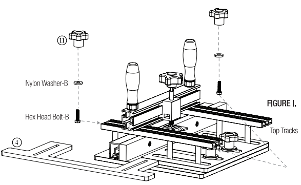
- Place one Nylon Washer-B onto each Hex Head Bolt-B and loosely thread on the two Knobs I to secure the Acrylic Guide to the Top Track.
- Setting the Acrylic Guide is outlined in Section II.
SETTING THE ACRYLIC GUIDE
Setting the Acrylic Guide only takes a minute, but is vital for proper operation.
- First, loosen the two Knobs I that secure the Acrylic Guide ® to the Top Track 3. FIGURE J.
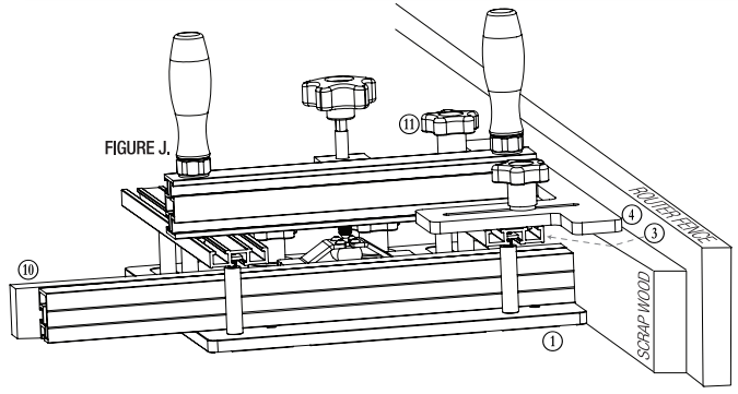
- Insert a straight 3/4″ scrap wood spacer between the Base ® and your router fence. The scrap wood spacer may need to be thicker for extremely deep routing cuts size your spacer to prevent contact.
- While holding the Iron-Grip Coping Sled up against the scrap wood spacer and the router fence, slide the Acrylic Guide up against the router fence and tighten the two Knobs.
- Remove the scrap wood spacer and keep the Acrylic Guide tight against the fence. Use the included 3/16″ Allen Wrench to loosen the Cap Screws on the Spoil Board I. Slide the Spoil Board forward so that it contacts the router fence and then tighten the Cap Screws to secure the Spoil Board in place. FIGURE K.
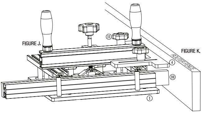
NOTE: The Acrylic Guide and the Spoil Board should be the only parts of the Coping Sled that run against the router fence during use. At no time should the Base come in contact with the router fence or the router bit. For large cutters, it may be necessary to use a wider spacer during setup.
INSTALLING YOUR WORKPIECE
- Install your workpiece by placing it on the Base. Ensure the Acrylic Guide is pressed tight against the fence, then slide the workpiece forward against the fence.
- Slide the Top Plate over to press the workpiece firmly against the Spoil Board and tighten the Knob.
- Position the Work Holding Clamp over the center of the board and turn the Knob to clamp the board in place.
- For a step-by-step on how to make rail and stile doors, scan this QR code. It will take you to our YouTube channel where you can learn how to get the most out of your Iron-Grip Coping Sled.
Scan the QR code above to watch the video or visit woodpeck.com under the video tab towards the bottom of the product page.
WARNING!
This product can expose you to chemicals, inducing chromium, which is known to the State of California to cause cancer and birth defects or other reproductive harm. For more information go to www.P65Wamings.ca.gov
- At Woodpeckers we are constantly reviewing & improving our tools. The most current version of our instruction manuals is always available to download/print at woodpeck.com via the tool’s page. (Located in the bottom section of the tool page under the “Additional Information” or “Instructions” tabs.)
- Be the first to know all the new products & sales by subscribing to our eClub. (Located at the top center of our webpage woodpeck.com.)
- Subscribe to our YouTube channel to stay up-to-date on all the latest tooltips & tricks.
- Could you interact with us? Follow us on Facebook & Instagram!
Woodpeckers, LLC Strongsville, Ohio
woodpeck.com
© 2021Woodpeckers. ILC
FAQs About Woodpecker Iron Grip Coping Sled
Which coping sled is the greatest?
Woodpeckers Using Sleds to Cope. When routing end grain, this is by far the best-coping sled available on the market for controlling the process. Excellent workmanship, lovely detailing, and a flexible design.
What is the purpose of a coping sled?
The coping sled serves a single, but very significant, purpose! assisting the woodworker in cutting a piece of work material across its end grain, or short end, to form the joint needed to assemble frame and panel—also known as rail and stile—doors.
In snow, why are sleds used?
A sled’s runners, or narrow, straight skids, support its body. Sleds are typically employed in places where wheeled vehicles would bog down or have trouble navigating, such as in Lapland and on the tundras of Alaska, Canada, and Asia.
Do plastic sleds work well?
In addition to being heavier than foam, plastic is significantly more resilient. It is therefore perfect for larger children or adults.
Are plastic sleds inferior to metal ones?
Wooden sleds generate more friction than metal ones, while plastic sleds are more frictional than wooden ones. However, a properly-maintained plastic sled free of dents can perform just as well as a metal one (albeit these flaws can slow you down). Success for you will also be predetermined.
Are inflatable sleds effective?
Depending on the specific inflatable, you can typically fit a couple of people on these sleds, which tend to move across the snow very swiftly. These require a decent hill because pulling them behind an ATV isn’t as effective and they are harder for people to pull.
How are sleds turned?
Two ropes that are fastened to a steering bolt and rotate the bobsled’s front frame make up the steering system.
Are there brakes on sleds?
Hydraulic disc brakes and an emergency parking brake are standard on snowmobiles. The brake lever, located on the left side of the handlebar, is used to progressively stop a sled.
What’s the name of the sleds?
Winter sports such as sledding, sledding, or sleighing are usually performed in a prone or seated position on a vehicle commonly referred to as a sled (North American), sled (British), or sleigh.
Why did people create sleds?
The first sleds were fashioned from wood, bone, and animal hide. The main use of these sleds was transportation in regions that received a lot of snowfall. As alternative modes of transportation developed over time, people started utilizing sleds for recreational purposes like hill-sliding and racing.
For more Manuals by Woodpecker, visit MANUALSDOCK

