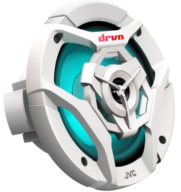
JVC CS-DR621 MWL Marine Speaker
About JVC
JVC (JVCKENWOOD Europe B.V.) is JVCKENWOOD Corporation’s wholly owned subsidiary. JVC is a renowned creator and manufacturer of sophisticated audio and video products that employ cutting-edge technologies to produce high-quality sound and visuals.
JVC provides high-definition displays and home theater projectors, digital video camcorders, home theater systems, audio components and systems, portable audio products, digital storage devices, audio and video accessories, and automobile audio/video products in its consumer products.
Parts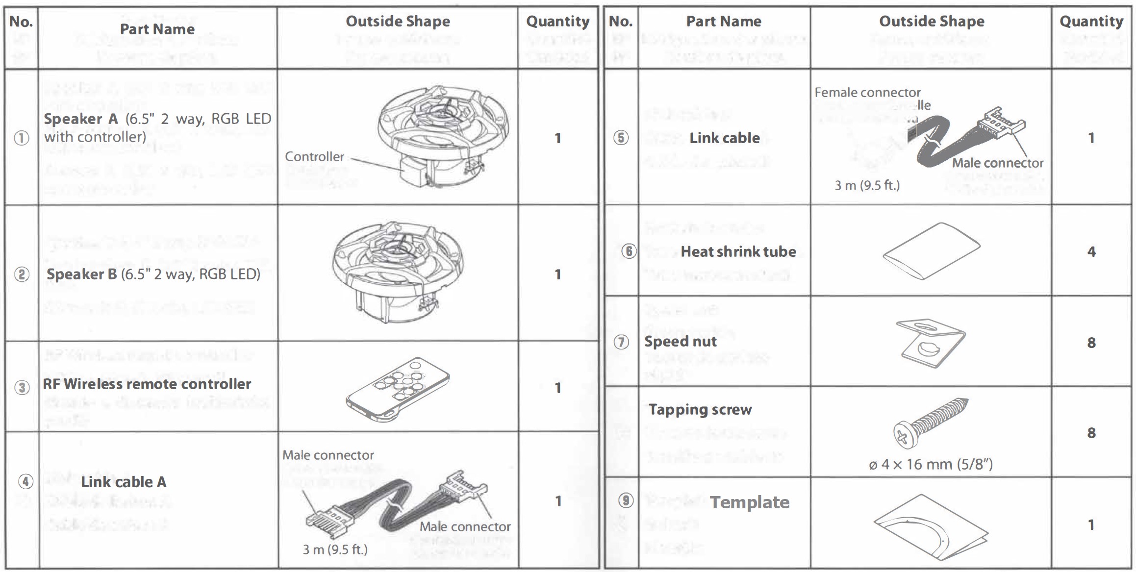
Connections
WARNING: Remove the ignition key and disconnect the negative terminals of the battery to prevent short circuits.
CAUTION: Check that no unconnected wires or connectors are touching the metal parts or car body.
Wiring
- In a computer-equipped boat/vehicle, when you remove the 0 terminal of the battery, the memory may disappear, or a defect may occur in the electrical system of the boat/vehicle. Consult your dealer for further details.
- Do not allow the wire to directly contact the edge of the iron plate by using grommets.
- Do not turn the power on if the ground wire is not connected.
Connect the ground wire to a metal part of the car chassis that acts as an electrical ground passing electricity to the battery’s negative terminals.
Connecting the speaker cords
With this product, the speaker cords are not supplied. Obtain the audio speaker cords with the required length. To connect the speaker cords to the speaker, terminate the wires with female spade connectors. 12 – 22 AWG speaker cord is recommended.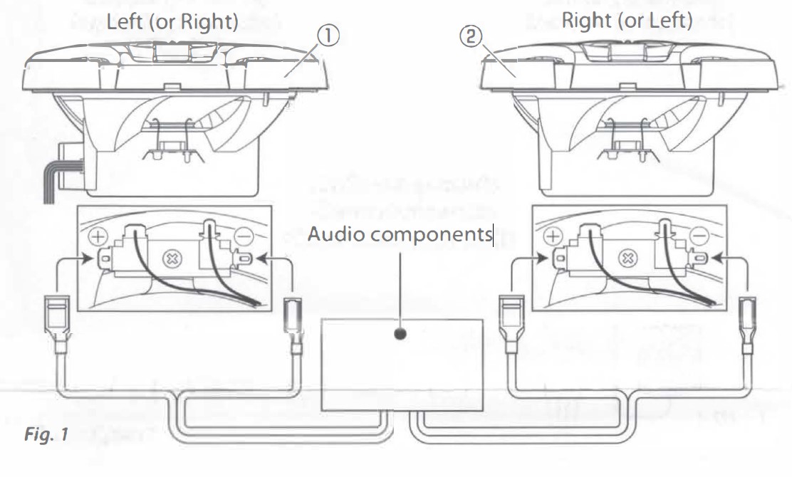
Connecting the power supply wires and link cable (RGB LED)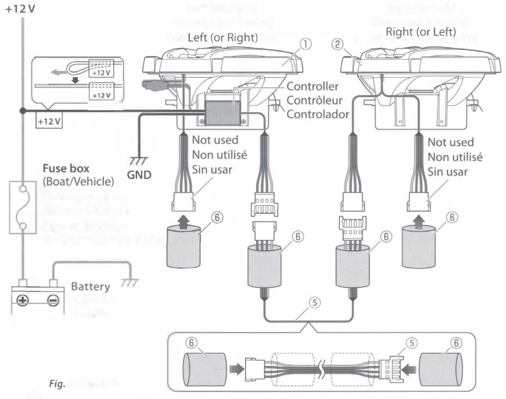
- Pass 2 heat shrink tubes (6) onto the link cable B (5).
- Connect the link cable B (5) to the left and right speakers.
- Put the heat shrink tube (6) over the connection area of the connector. Apply heat with a heat gun or similar to shrink the tube and protect the connector from moisture, etc.
Protect the 2 connectors that are not in use with heat shrink tubes (6)· - Connect the ground wire (black) and the + 12 V wire (yellow) of the controller of speaker AG).
- Reconnect the negative terminal of the battery.
Do not use link cable A (4) for this connection.
Do not connect the + 12 V wire and ground wire in reverse. Incorrect connections can cause failure.

When connecting the power supply (+12 V) directly to the battery
CAUTION: Be sure to connect a 3 A fuse between the power cord(+ 12 V) of the controller of speaker AG) and the battery. The cord length between the battery and the fuse must not exceed 90 mm (3-9/16″).
Do not connect the+ 12 V wire and ground wire in reverse. Incorrect connections can cause failure.
When using multiple pairs of speakers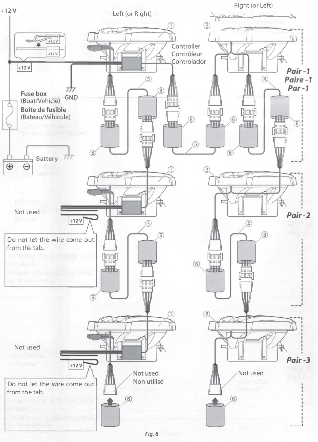
A maximum of up to 6 pairs of speakers can be + 12 V connected.
Connect the link cables of the second and subsequent pairs of speakers as shown on the right.
The figure shows an example of connecting 3 pairs of speakers. Connect the fourth and subsequent pairs of speakers in the same way as the third pair.
Protect the 2 connectors that are not in use with heat shrink tubes (6)· You can control all the LED lights with one remote controller, but you cannot control just a specific speaker.
Installation
Speaker locations
How to use the template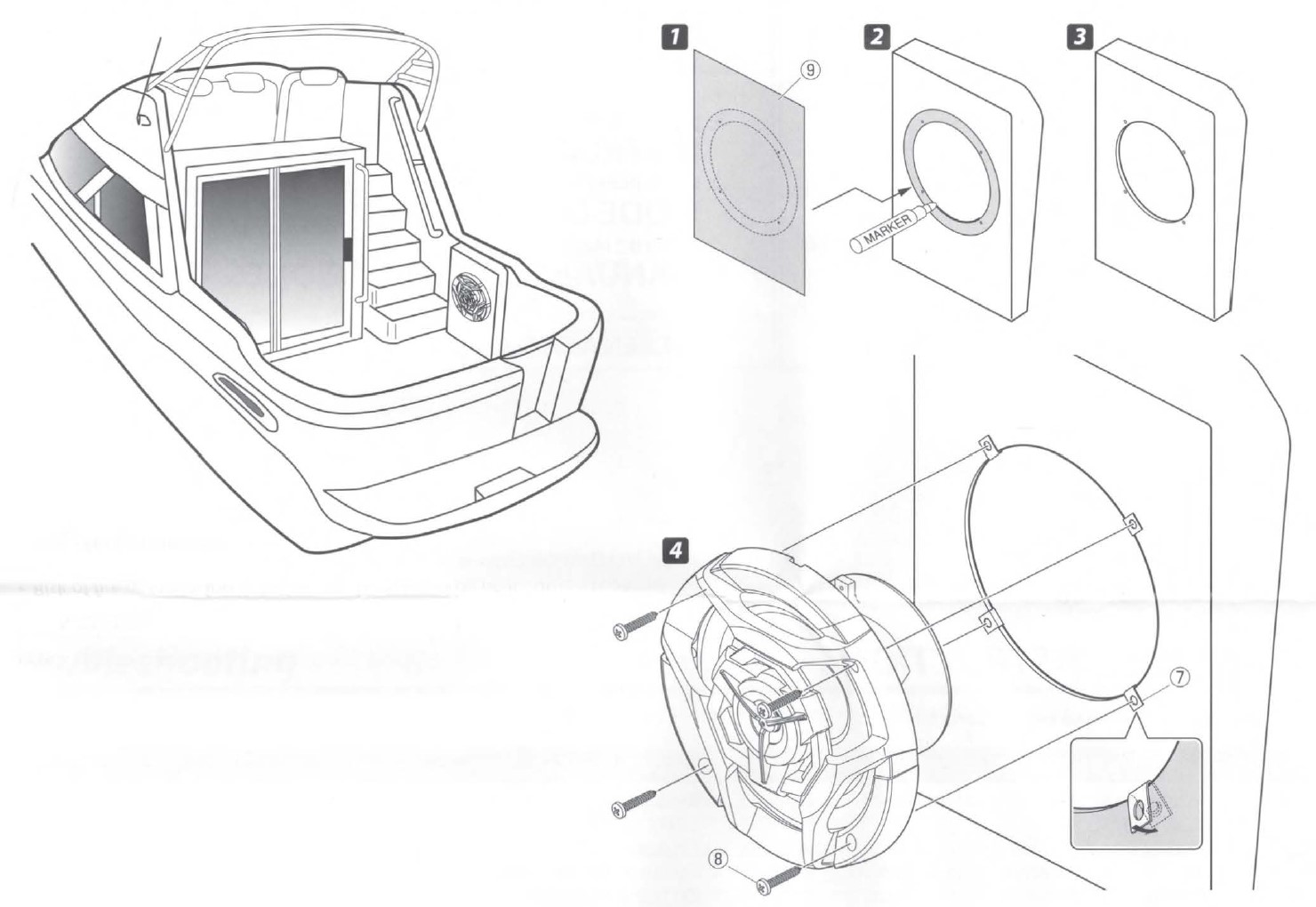
Controls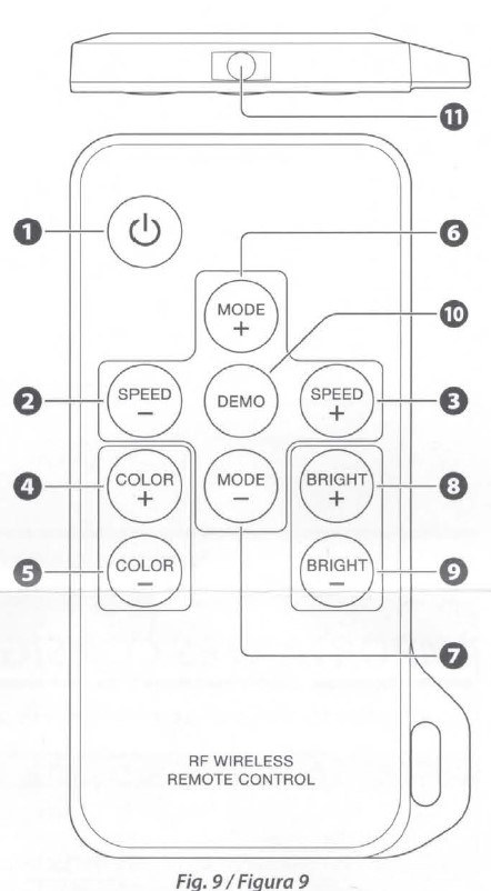
CAUTION: Do not leave or install the remote control in hot places such as on the dashboard.
- (Turn on/Standby): Press to switch the LED lights of the speakers ON/OFF (standby mode).Last memory function
When the product is turned on, it will operate in its pre-vious status. - SPEED -: Dynamic speed adjust
Adjust dynamic playing speed. Press SPEED+ to increase speed and press SPEED – to decrease speed. Adjust speed: 7 steps - SPEED +: Dynamic speed adjust
Adjust dynamic playing speed. Press SPEED+ to increase speed and press SPEED – to decrease speed. Adjust speed : 7 steps - COLOR +:Static color adjust
Switch to static color mode from dynamic mode, or switch between different static colors. Select Color: 21 colors - COLOR -: Static color adjust
Switch to static color mode from dynamic mode, or switch between different static colors. Select color: 21 colors - MODE +:Dynamic modes adjust
Switch to dynamic mode from static color mode, or switch between dynamic modes.
Select mode: 21 modes - MODE -: Dynamic modes adjust
Switch to dynamic mode from static color mode, or switch between dynamic modes.
Select mode : 21 modes - BRIGHT +: Brightness adjust
Adjust static color brightness. Press BRIGHT+ to increase brightness and press BRIGHT – to decrease.
Adjust brightness: 8 steps - BRIGHT -: Brightness adjust
Adjust static color brightness. Press BRIGHT+ to increase brightness and press BRIGHT – to decrease.
Adjust brightness: 8 steps - DEMO: Switching to the demo mode
Press the MODE(+/-) key to exit the demo mode. - Signal transmission indicator: The LED lights up in red when a key is pressed and a signal is transmitted.
Pull out the insulation sheet when using it for the first time.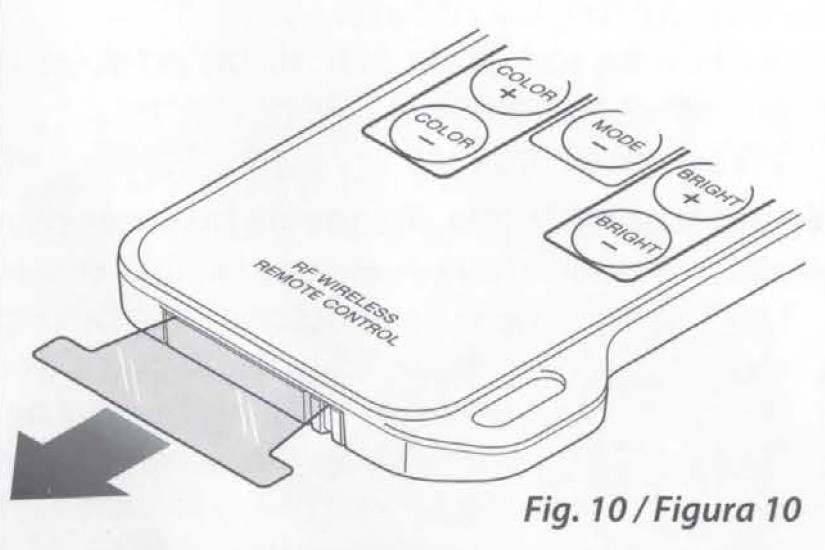
How to replace the battery
If the Remote Controller operates only over shorter distances or does not operate at all, it is possible that the battery is depleted. In such instances, replace the battery with a new one.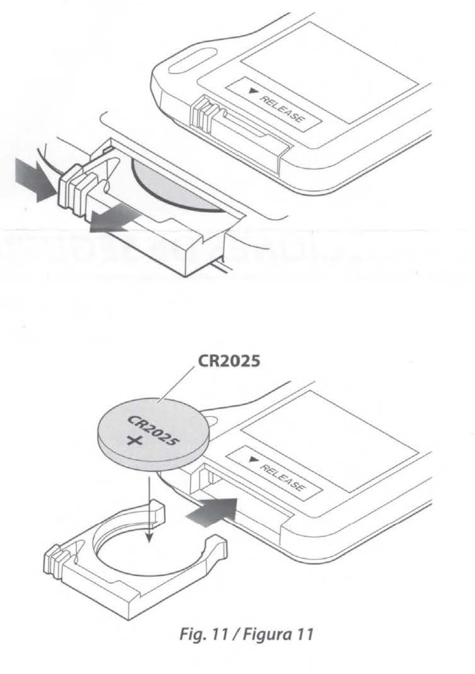
CAUTION
- Risk of fire or explosion if the battery is replaced by an incorrect type. Use a button battery CR2025 (use only the approved battery).
- Risk of fire, explosion, or the leakage of flammable liquid or gas if the battery is left in an extremely high temperature surrounding environment and/or subjected to extremely low air pressure. The battery pack or batteries shall not be exposed to excessive heat such as sunshine, fire or the like.
- Risk of fire, explosion, or the leakage of flammable liquid or gas if the battery is disposed into fire or a hot oven, recharged, shorted, mechanically crushed, or cut off the battery.
- If spilled fluid comes in contact with your eyes or on clothing, immediately rinse with water and consult a physician.
Troubleshooting
Often, what appears to be a malfunction is due to user error. Before calling for service, please consult the following table.
Specifications
Design and specifications are subject to change without notice.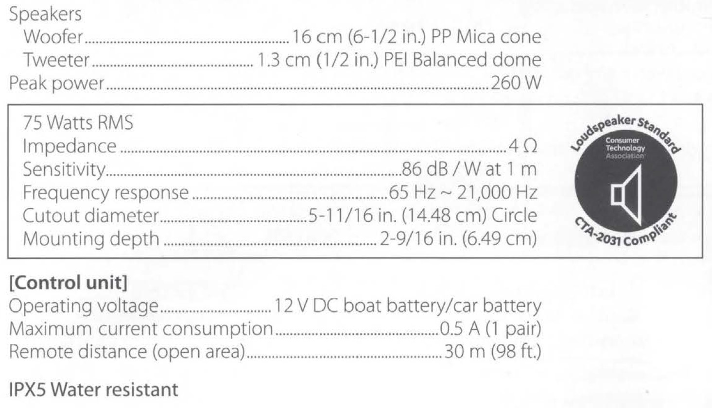
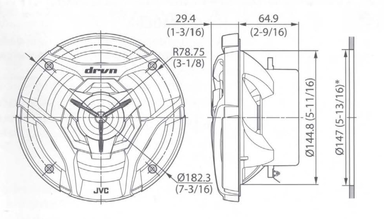 * Mounting hole
Unit: mm (inch)
FCC CAUTION
Changes or modifications not expressly approved by the party responsible for compliance could void the user’s authority to operate the equipment.
NOTE: This equipment has been tested and found to comply with the limits for a Class B digital device, pursuant to part 15 of the FCC Rule. These limits are designed to provide reasonable protection against harmful interference in a residential installation. This equipment generates, uses, and can radiate radio frequency energy if not installed. However, there is no guarantee that interference will not occur in a particular installation. If this equipment does cause harmful interference to radio or television reception, which can be determined by turning the equipment off and on, the user is encouraged to try to correct the interference by one or more of the following measures:
- Reorient or relocate the receiving antenna.
- Increase the separation between the equipment and the receiver.
- Connect the equipment to an outlet on a circuit different from that to which the receiver is connected.
Supplier’s Declaration of Conformity
- Trade Name: JVC
- Products: SPEAKER
- Model Name: CS-DR621 MWL / CS-DR620MBL
- Responsible Party: JVCKENWOOD USA CORPORATION, 2201 East Dominguez Street, Long Beach, CA 90810, U.S.A. PHONE: 310 639-9000
THIS DEVICE COMPLIES WITH PART 15 OF THE FCC RULES. OPERATION IS SUBJECT TO THE FOLLOWING TWO CONDITIONS:
- THIS DEVICE MAY NOT CAUSE HARMFUL INTERFERENCE, AND
- THIS DEVICE MUST ACCEPT ANY INTERFERENCE RECEIVED, INCLUDING INTERFERENCE THAT MAY CAUSE UNDESIRED OPERATION.
CALIFORNIA, USA ONLY
This product contains a CR Coin Cell Lithium Battery which contains Perchlorate Materialspecial handling may apply.
See www.dtsc.ca.gov/hazardouswaste/perchlorate
For more manuals by JVC, Visit Manualsdock
[embeddoc url=”https://manualsdock.com/wp-content/uploads/2023/08/JVC-CS-DR621-MWL-Marine-Speaker-Instruction-Manual.pdf” download=”all”]


