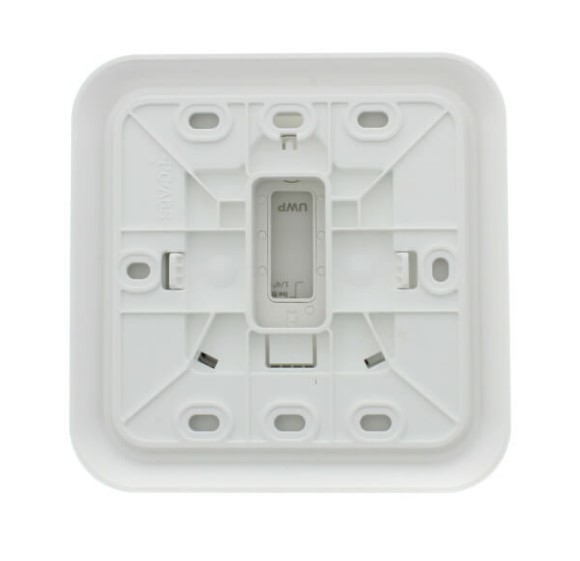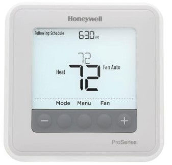
Honeywell T6 Pro Programmable Thermostat
About Honeywell
The corporate headquarters of the American multinational conglomerate Honeywell International Inc. is in Charlotte, North Carolina. Aerospace, building technologies, performance materials and technology, and safety and productivity solutions make up its four main business sectors.
Optional Cover Plate Installation
NOTE: If an Optional Cover Plate is not required, see “UWP Mounting System installation” on the next page. Use the Optional Cover Plate when you need to cover the paint gap from the old thermostat. There are different cover plates depending on when the thermostat was manufactured.
For the square cover plate:
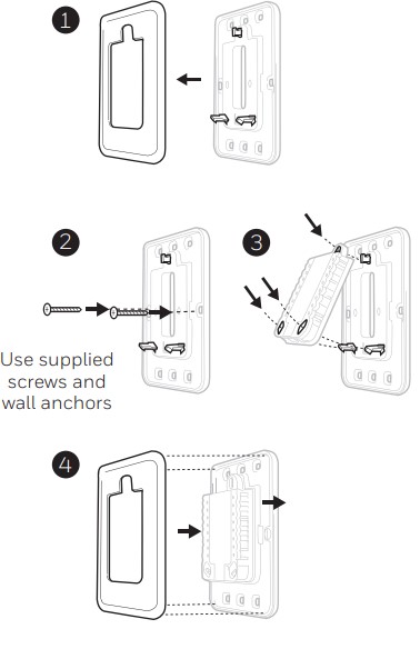
- Separate the Cover Plate from Mounting Plate.
- Mount the Mounting Plate onto the wall using any of the 8 screw holes. Insert and tighten the mounting screws supplied with Cover Plate Kit. Do not over-tighten. See Figure Make sure the Mounting Plate is level.
- Attach the UWP by hanging it on the top hook of the Mounting Plate and then snapping the bottom of the UWP in place. See Figure 3.
- Snap the Cover Plate onto the Mounting Plate. See Figure 4.
For the rectangular cover plate:
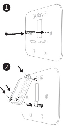
- Mount the Cover Plate on the wall using any of the 6 screw holes. Insert and tighten the mounting screws supplied with the Cover Plate. Do not over-tighten. See Figure 1. Make sure the Cover Plate is level. Attach the UWP by hanging it on the top hook of the Cover Plate and then snapping the bottom of the UWP in place. See Figure 2.
- If there are no existing wall anchors:
- Position the Cover Plate on the wall. Level and mark hole positions. See Figure 1.
- Drill holes at marked positions, and then lightly tap supplied wall anchors into the wall using a hammer.
- If your box contains red anchors, drill 7/32” (5.6 mm) holes.
- If your box contains yellow anchors, drill 3/16” (4.8 mm) holes.
- Use 2x supplied screws (#8 1-1/2” (38 mm) for red anchors and #6 1-1/2” (38 mm) for yellow anchors).
UWP Mounting System Installation
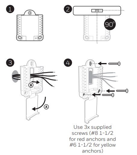
- Before starting, turn the power off at the breaker box or switch. Open the package to find the UWP. See Figure 1.
- Position the UWP on the wall. Level and mark hole positions. See Figure 2. Drill holes at marked positions, and then lightly tap supplied wall anchors into the wall using a hammer.
- If your box contains red anchors, drill 7/32” holes.
- If your box contains yellow anchors, drill 3/16” holes.
- Pull the door open and insert the wires through the wiring hole of the UWP. See Figure 3.
- Place the UWP over the wall anchors. Insert and tighten mounting screws supplied with the UWP. Do not over-tighten. Tighten until the UWP no longer moves. Close the door. See Figure 4.
Power options
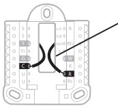
Insert R and C wires into designated terminals for primary AC power (The c terminal is optional if batteries are installed, but it is recommended). Remove wires by depressing the terminal tabs.
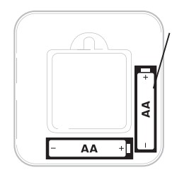
Insert AA batteries for primary or backup power.
Setting Slider Tabs
Set R Slider Tab.
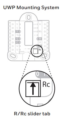
- Use a built-in jumper (R Slider Tab) to differentiate between one or two transformer systems.
- If there is only one R wire, and it is connected to the R, Rc, or RH terminal, set the slider to the up position (1 wire).
- If there is one wire connected to the R terminal and one wire connected to the Rc terminal, set the slider to the down position (2 wires).
NOTE: Slider Tabs for U terminals should be left in place for T6 Pro models.
Wiring terminal designations
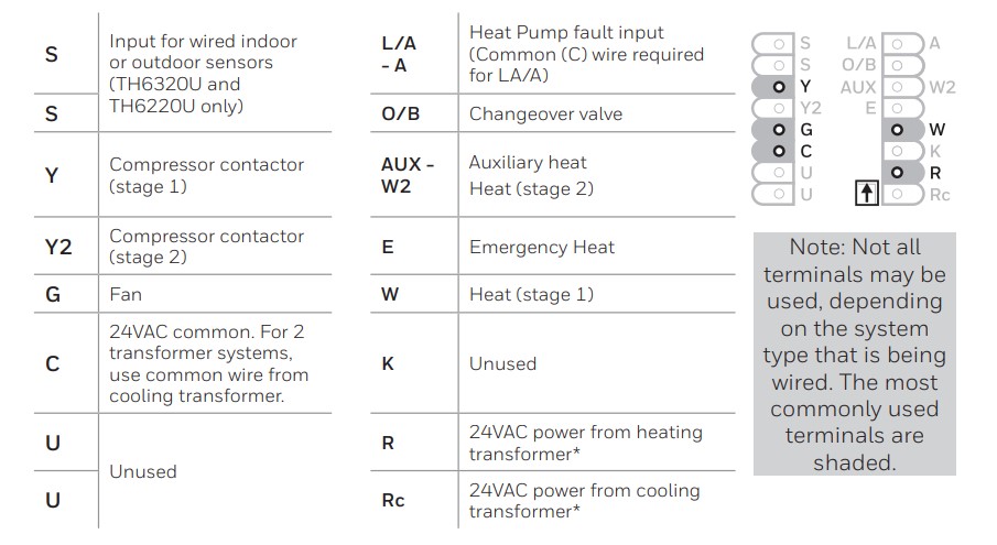
* Terminal can be jumped using Slider Tab. See “Setting Slider Tabs” above.
Wiring conventional systems: forced air and hydronic Shaded areas below apply only to TH6320U/TH6220U or as otherwise noted.
1H/1C System (1 transformer)
- R Power [1]
- Rc [R+Rc joined by Slider Tab] [2]
- Y Compressor contactor
- C 24VAC common [3]
- W Heat
- G Fan
Heat-only System
- R Power [1]
- Rc [R+Rc joined by Slider Tab] [2]
- C 24VAC common [3]
- W Heat
Heat-only System (Series 20) [5]
- R Series 20 valve terminal “R” [1]
- Rc [R+Rc joined by Slider Tab] [2]
- Y Series 20 valve terminal “W”
- C 24VAC common [3]
- W Series 20 valve terminal “B”
Heat-only System (power open zone valve) [5]
- R Power [1]
- Rc [R+Rc joined by Slider Tab] [2]
- W Valve
- C 24VAC common [3]
1H/1C System (2 transformers)
- R Power (heating transformer) [1]
- Rc Power (cooling transformer) [1]
- Y Compressor contactor
- C 24VAC common [3, 4]
- W Heat
- G Fan
Heat-only System with Fan
- R Power [1]
- Rc [R+Rc joined by Slider Tab] [2]
- C 24VAC common [3]
- W Heat
- G Fan
Cool-only System
- R Power [1]
- Rc [R+Rc joined by Slider Tab] [2]
- Y Compressor contactor
- C 24VAC common [3]
- G Fan
2H/2C System (1 transformer) [6]
- R Power [1]
- Rc [R+Rc joined by Slider Tab] [2]
- Y Compressor contactor (stage 1)
- C 24VAC common [3]
- W Heat (stage 1)
- G Fan
- W2 Heat (stage 2)
- Y2 Compressor contactor (stage 2)
NOTES Wire specifications: Use 18- to 22-gauge thermostat wire. A shielded cable is not required.
- Power supply. Provide disconnect means and overload protection as required.
- Move R-Slider Tab on UWP to the R setting. For more information, see “Setting Slider Tabs” on page 3
- Optional 24VAC common connection.
- The common connection must come from the cooling transformer.
- In ISU set the Heat system type to Radiant Heat. Set the number of cool stages to 0.
- In Installer Setup, set the system type to 2Heat/2Cool Conventional.
Wiring heat pump systems Shaded areas below apply only to TH6320U/TH6220U or as otherwise noted.
1H/1C Heat Pump System
- R Power [1]
- Rc [R+Rc joined by Slider Tab] [2]
- Y Compressor contactor
- C 24VAC common [3]
- O/B Changeover valve [7]
- G Fan
- W Do not use this terminal for heat pump applications!
2H/1C Heat Pump System [8]
- R Power [1]
- Rc [R+Rc joined by Slider Tab] [2]
- Y Compressor contactor
- C 24VAC common [3]
- O/B Changeover valve [7]
- G Fan
Aux Auxiliary heat
- E Emergency heat
- L Heat pump fault input
- W Do not use this terminal for heat pump applications!
2H/2C Heat Pump System (TH6320U only) [9]
- R Power [1]
- Rc [R+Rc joined by Slider Tab] [2]
- Y Compressor contactor (stage 1)
- C 24VAC common [3]
- O/B Changeover valve [7]
- G Fan
- Y2 Compressor contactor (stage 2)
- L Heat pump fault input
- W Do not use this terminal for heat pump applications!
3H/2C Heat Pump System (TH6320U only) [10]
- R Power [1]
- Rc [R+Rc joined by Slider Tab] [2]
- Y Compressor contactor (stage 1)
- C 24VAC common [3]
- O/B Changeover valve [7]
- G Fan
- Aux Auxiliary heat
- E Emergency heat
- Y2 Compressor contactor (stage 2)
- L Heat pump fault input
- W Do not use this terminal for heat pump applications!
Dual Fuel System (TH6320U / TH6220U only)
- R Power [1]
- Rc [R+Rc joined by Slider Tab] [2]
- Y Compressor contactor (stage 1)
- C 24VAC common [3]
- O/B Changeover valve [7]
- G Fan
- Aux Auxiliary heat
- E Emergency heat
- Y2 Compressor contactor (stage 2 – if needed) [11]
- L Heat pump fault input
- S Outdoor sensor
- S Outdoor sensor
- W Do not use this terminal for heat pump applications!
NOTES Wire specifications: Use 18- to 22-gauge thermostat wire. A shielded cable is not required.
- Power supply. Provide disconnect means and overload protection as required.
- Move R-Slider Tab on UWP to the R setting. For more information, see “Setting Slider Tabs” on page 3
- Optional 24VAC common connection.
- In Installer Setup, set the system type to 2Heat/2Cool Conventional.
- In Installer Setup, set the changeover valve to O (for cool changeover) or B (for heat changeover).
- In ISU set the Heat system type to the Heat pump. 1 compressor and 1 stage of backup heat.
- In ISU set the Heat system type to the Heat pump. 2 compressors and 0 stages of backup heat.
- In ISU set the Heat system type to the Heat pump. 2 compressors and 1 stage of backup heat.
- Dual fuel with Y2 only for TH6320U.
Thermostat mounting
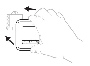
- Push excess wire back into the wall opening.
- Close the UWP door. It should remain closed without bulging.
- Align the UWP with the thermostat, and push gently until the thermostat snaps in place.
- Turn the power on at the breaker box or switch.
Set the time and date
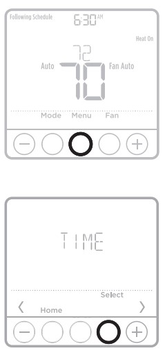
Time
- Press Menu on your thermostat.
- Press + or – to go to TIME. Press Select.
- Press + or – to choose between 12 or 24 hours. Press Select.
- Use + or – to adjust the hour. Press Select.
- Use + or – to adjust the minutes. Press Select to exit the Time menu.
Date
- If previously set time, continue to Step
- If at the Home screen, press Menu on your thermostat.
- Press + or – to go to DATE. Press Select.
- Use + or – to adjust the year. Press Select.
- Use the + or – to adjust the month. Press Select.
- Use the + or – to adjust the day. Press Select to save and exit the Date menu.
System operation settings
- Press the Mode button to cycle to the next available System mode.
- Cycle through the modes until the required System mode is displayed and leave it to activate.
NOTE: Available System modes vary by model and system settings.
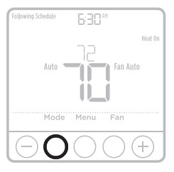
System modes:
- Auto
- Heat
- Cool
- Em Heat
- Off
Fan operation settings
- Press the Fan button to cycle to the next available Fan mode.
- Cycle through the modes until the required Fan mode is displayed and leave it to activate.
NOTE: Available Fan modes vary with system settings.
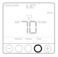
Fan modes:
- Auto: The fan runs only when the heating or cooling system is on.
- On: The fan is always on.
- Circ: The fan runs randomly about 33% of the time.
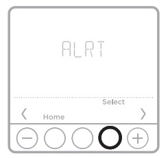
Alerts or Reminders*
- Press Menu, and then press until the display shows ALRT.
- Press Select to display which alert(s) are present.
- The word SNZE (SNOOZE) appears.
- Press Select again to snooze the reminder for 7 days.
- To clear the alert, press Select, and then press Go to CLER (Clear).
- Press Select to clear the reminder.
* Some alerts cannot be snoozed or cleared. Please call your local heating and cooling professional if this occurs. The heating and cooling system may require service.
FAQs Honeywell T6 Pro Programmable Thermostat
Is there an auto mode on the Honeywell T6 Pro Programmable Thermostat?
Automatic switch from heat to cool: When Auto mode is selected, the T6 Pro Z-Wave thermostat will automatically determine whether your home requires heating or cooling in order to achieve the desired temperature at the appropriate time.
How do I programme my Honeywell T6 Pro Programmable Thermostat?
Setting the temperature on your Honeywell thermostat is simple if you have a manual thermostat. To adjust the temperature, simply press the up and down buttons. The temperature you set will remain until you change it again.
Is it possible to connect my Honeywell T6 Pro Programmable Thermostat to my phone?
Honeywell’s dependable and well-reviewed app lets you programme your thermostat from your computer, tablet, or smartphone, whether you’re across the room or halfway around the world.
What is the Honeywell T6 Pro Programmable Thermostat password?
The lock password for a Honeywell T6 Pro Programmable Thermostat is the sum of the Date Code and the number 1234.
How do I change the setting on my Honeywell T6 Pro Programmable Thermostat to automatic?
When it says “auto cool,” you must first press the mode button until the mode changes to “heat,” then use the + or – to change the heat set-point. Then, press the mode button to return to Auto Changeover mode.
How do I change the setting on my Honeywell T6 Pro Programmable Thermostat to automatic?
When it says “auto cool,” you must first press the mode button until the mode changes to “heat,” then use the + or – to change the heat set-point. Then, press the mode button to return to Auto Changeover mode.
What temperature should I set my air conditioner to?
According to the Department of Energy1, the ideal temperature for air conditioners to balance energy savings and comfort when people are at home and need cooling is 78° Fahrenheit.
What are the best auto thermostat settings?
It’s best to keep your thermostat set to 68 degrees or less during the winter. Keep your thermostat at 75 degrees or higher during the summer.
Is it possible to use a programmable thermostat manually?
Unfortunately, many homeowners operate their programmable thermostats in the same way they would an analogue thermostat—by manually raising or lowering the temperature. Don’t programme your thermostat incorrectly, and don’t turn off the programmable feature. For more information, refer to your owner’s manual.
For more manuals by Honeywell, Visit Manusladock
[embeddoc url=”https://manualsdock.com/wp-content/uploads/2023/02/Honeywell-T6-Pro-Programmable-Thermostat.pdf” download=”all”]

