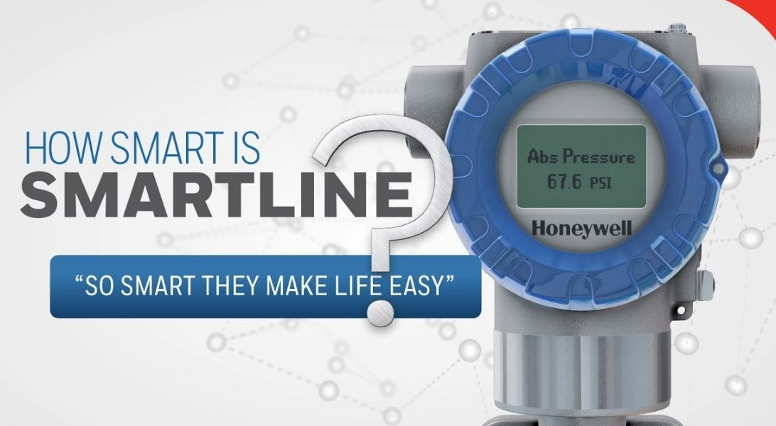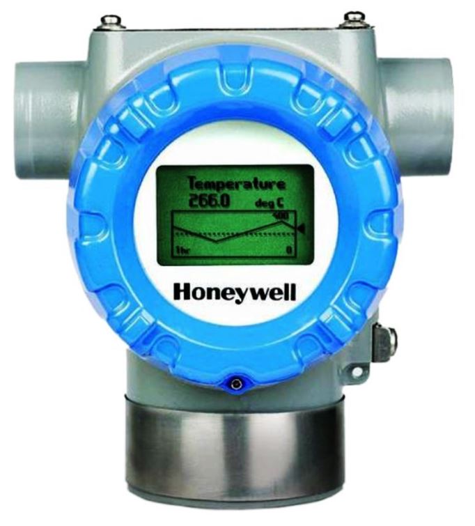
Honeywell STT700 SmartLine Temperature Transmitter
Documentation
To access complete documentation, including language variants, scan the QR code below using your smartphone/device or QR code scanner. Go to the APP store for your free Smartphone QR scanner Or you can follow the URL to access the online SmartLine HUB page. The HUB page will contain direct links to open SmartLine product documentation.
URL
https://hwll.co/SmartLineHUB
QR Code

Installation
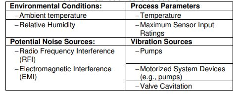
For start-up, operation (including configuration), maintenance, and calibration refer to the STT700 Transmitter User’s manual, #34-TT-25-17 Evaluate the site selected for the Transmitter installation concerning the process system design specifications and Honeywell’s published performance characteristics for your particular model. Conditions to be considered include:
Table 1: Installation considerations
In preparation for post-installation processes, refer to the MC Toolkit User Manual, Document # #34-ST-25-50 (MCT404), for battery conditioning and device operation and maintenance information.
DEVICE CONFIGURATION
This transmitter comes with a standard factory configuration. Consult the nameplate for basic information. Reconfiguration for your particular application can be accomplished by following instructions in the Transmitter User’s manual. This can be found by following the website URL or QR code on page 1 of this document.
Features and Options
As shown in Figure 1, the STT700 is packaged in a single module. The elements in this module are connected to the process sensors, measure the process variables, respond to setup commands, and execute the software and protocol for the different temperature measurement types.
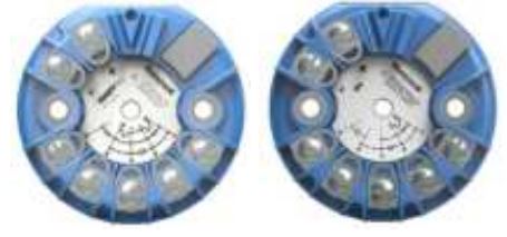
Figure 1 – STT700 Temperature Transmitter (HART left, DE right)
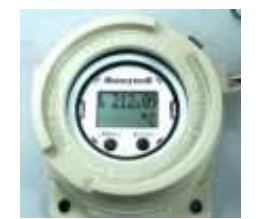
Figure 2 – STT700 Temperature Transmitter with display module
The transmitter measures process temperature and outputs a signal proportional to the measured process variable (PV). Available output communication protocols include 4 to 20mA, Honeywell Digitally Enhanced (DE), and HART protocols.
Mounting the Transmitter
DIN Rail Mounting
If the STT700 is to be installed on DIN Rail then the main considerations are electrical connections and mechanical fixing. Electrical connections are identical to the bench test instructions except that thermocouple wire is likely to be used with thermocouples. Mechanical fixing of the module is using the snap-in DIN Rail Clips which are screwed to the bottom lugs of the module.
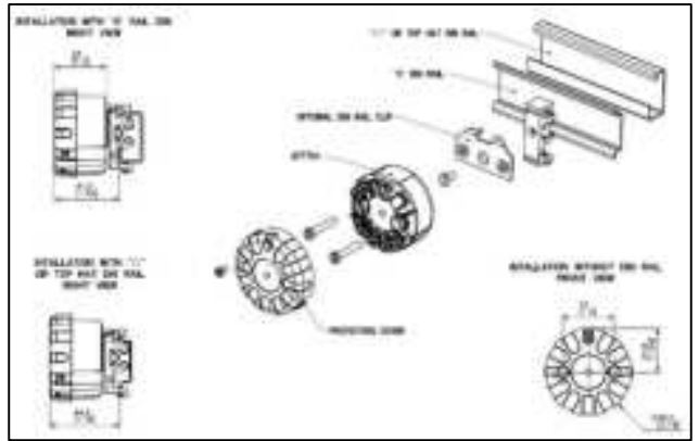
Uninstalling/Installing EU Meter from Housing EU Meter:
- Remove the EU METER from the mounting bracket.
- Unfasten the 2 mounting screws.
- Remove the bracket.
Mounting Module in Housing
The STT700 module can be installed in a variety of housings suitable for direct head mounting, 2” (50mm) pipe mounting, or wall mounting.
Table 2: Mounting Dimensions

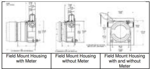
Figure 4: Wall Mounting Dimensions
Spring Loading
Spring loading is available worldwide with direct head mounting. In North America, spring loading is typically included in the sensor/thermowell assembly and is available with all housings. For non-North American spring loading as shown in Figure 6, simply include the springs under the 33 mm pitch mounting screws, pass the screws through the module and sensor mounting plate and snap in the retaining circlip to the screws to hold the assembly together. Guide the sensor assembly through the housing sensor entry and screw down the 33 mm screws until the limit is reached as the sensor presses against the bottom of the thermowell.
For wall or 2” pipe mounting, the temperature sensor can be remote from the STT700 field mount housing or integral to the housing. For remote installations, the sensor wiring should be run in shielded, twisted pair wiring and connected via one of the housing wiring entries. For explosion-proof/flameproof installations, ensure that the cable entries are fitted with flameproof adaptors and that the wiring grade complies with local standards. For more details on wiring and dimensions for the Aluminum Direct head and Cast iron Direct head refer to the STT700 SmartLine transmitter user’s manual, #34-TT-25-17.
Wiring Variations
The above procedures are used to connect power to a transmitter. For loop wiring and external wiring, detailed drawings are provided for transmitter installation in non-intrinsically safe areas and intrinsically safe loops in hazardous area locations. This procedure shows the steps for connecting power to the transmitter. The screw terminals are suitable for wirings up to (16AWG)
- Shielded, twisted-pair cable such as Belden 9318 or equivalent must be used for all signal/power wiring.
Note:
If solid core wire is used strip insulation 1/4 in (6 mm). Once inserted under the square washer the stripped portion should be contained under the square washer. If multi-stranded wire is used, a ferrule is to be used and the stripped wire should be in the insulated portion of the ferrule. The ferrule can also be used on the solid core wire. - The cable shield must be connected at only one end of the cable. Connect it to the power supply side and leave the shield insulated at the transmitter side.
LIGHTNING PROTECTOR
This device is designed to give the SmartLine temperature transmitter maximum protection against surges such as those generated by lightning strikes. The lightning protector mounts right on the top of the STT700 terminal block, providing easy field wiring and also protection for the EU meter if used. For more details refer to the STT700 SmartLine temperature transmitter user’s manual, #34-TT-25-17.
Installation
- If an EU meter is used, remove the shunt on the Lightning Protector. In all other cases, the shunt must be present.
- If Standard Display is used, no need to remove the shunt.
- Remove the cover/cap of the housing (if applicable). The device fits on the top of the transmitter module terminal block and the transmitter output screws (+ and -) fix mechanically the device.
- If Standard Display is used, remove the cover of the housing and connect the display cable to the 8-pin connector provided on the transmitter.
- Attach the grounding wire to the ground screw in the housing. Connect a wire from the transmitter enclosure to local earth ground. Use size 14 AWG or 2.0mm2 bare or green covered wire.
- If an EU meter is used, wire according to
- If Standard Display is used, wire according.
- Connect the 4 – 20mA loop to the + and – terminal screws of the surge protection and close the cap of the housing.
Transmitter in Enclosure Selections:
Consult the manufacturer for dimensional information on the flameproof joints for repair. The painted surface of the Aluminum Enclosure may store electrostatic charge and become a source of ignition in applications with a low relative humidity of less than approximately 30% relative humidity where the painted surface is relatively free of surface contamination such as dirt, dust, or oil. Cleaning of the painted surface should only be done with a damp cloth.
The enclosure is manufactured from low copper aluminum alloy. In rare cases, ignition sources due to impact and friction sparks could occur. This shall be considered during Installation, particularly ifth equipment is installed at a Zone 0 location. If a charge-generating mechanism is present, the exposed metallic part on the enclosure is capable of storing a level of electrostatic that could become Incendive for IIC gases.
Therefore, the user/ installer shall implement precautions to prevent the buildup of electrostatic charge, e.g. earthing the metallic part. This is particularly important if equipment is installed in a Zone 0 location. For Installation of the NPT Plug or Adapter follow instructions as outlined in 34- XY-33-03.
WARRANTY/REMEDY
Honeywell warrants goods of its manufacture as being free of defective materials and faulty workmanship. Contact your local sales office for warranty information. If warranted goods are returned to Honeywell during the period of coverage, Honeywell will repair or replace without charge those items it finds defective. The foregoing is Buyer’s sole remedy and is instead of all other warranties, expressed or implied, including those of merchantability and fitness for a particular purpose.
Specifications may change without notice. The information we supply is believed to be accurate and reliable as of this printing. However, we assume no responsibility for its use. While we provide application assistance personally, through our literature and the Honeywell website, it is up to the customer to determine the suitability of the product in the application.
For more information
To learn more about SmartLine transmitters, visit https://process.honeywell.com/ Or contact your Honeywell Account manager.
Process Solutions
Honeywell 1250 W Sam Houston Pkwy S Houston, TX 77042 Honeywell Control Systems Ltd Honeywell House, Skimped Hill Lane Bracknell, England, RG12 1EB 34-TT-25-19 Rev.7 May 2023 ©2023 Honeywell International Inc. Shanghai City Centre, 100 Jungi Road Shanghai, China 20061 https://process.honeywell.com/
FOR MORE MANUALS BY HONEYWELL, VISIT MANUALSDOCK

