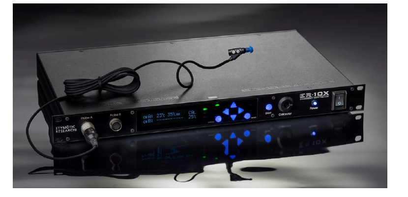
Etymotic ER10X Hearing Test Instrument
About Etymotic
Etymotic is a well-known audio technology business that specializes in high-quality earphones and hearing devices. Since its founding in 1983 by Dr. Mead Killion as a pioneer in audio technology, the firm has built a reputation for its dedication to accurate sound reproduction and hearing protection. Etymotic has earned the trust of audiophiles and professionals alike by focusing on research and innovation.
Their devices are intended to provide great sound quality while protecting consumers’ hearing health. These items have found applications in a variety of industries, including aviation, music, construction, and others, guaranteeing that people’s hearing is protected without affecting their ability to hear accurately.
Introduction
The purpose of the ER·10X extended bandwidth research probe system is to allow for low-noise otoacoustic measurement over a larger bandwidth used for diagnostic evaluation of the middle and inner ear components of hearing. This system will produce well-calibrated, high-quality acoustic stimuli that cover the full frequency range of human hearing, including the highest frequencies that activate the part of the cochlea most easily damaged by ototoxic drugs, noise, and the normal process of aging. The microphones and sound sources in the probes will allow accurate presentation of acoustic stimuli or measure the acoustic emissions generated by the inner ear.
System Overview
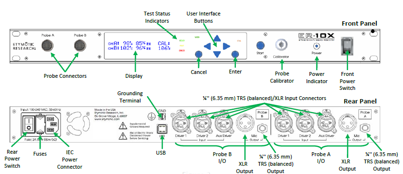
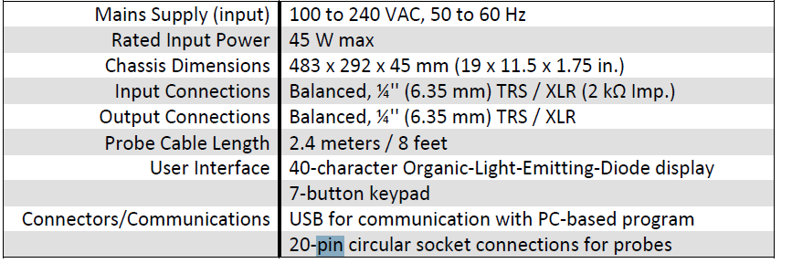
The system consists of the control unit, probe, single-use ear tips, replaceable probe tubes, and other accessories. The ER·10X instrument contains the hardware and software to elicit test stimuli. The rack-mountable chassis contains circuit boards that provide signal processing and display probe information. The instrument uses a 2×20 organic light-emitting diode display (OLED) and six light-emitting diodes (LEDs) to provide a visual display of the status to the operator. Seven tactile-type, LED-illuminated push buttons located on the front of the instrument allow the user to control testing.
The probe houses 3 receivers, a microphone, a combination I2C humidity/temperature sensor, a backup thermistor, and a variable-power heating element. The probe is meant to be used to produce test stimuli and measure the sound pressure level (SPL) present in the sealed ear canal. The interface of the instrument to the ear canal is accomplished through ear tips, which fit onto the probe tube. The ear tips are color-coded to facilitate easy selection by size.
WARNING
This equipment should be checked prior to any contact to the testing subject related to the volume control for the external source feeding the console to ensure that no possible hearing damage can be caused. Low outputs should be set before connecting equipment to the subject.
Features of the ER·10X Extended Bandwidth Research Probe System
The intent of this new probe system is to enhance the performance and capabilities of the current ER-10B+ and ER-10C probe systems and expand capacity in the following areas:
- Extended operating bandwidth beyond 20 kHz
- Extended dynamic range
- Reduced noise and distortion artifacts
- Reduced electrical and acoustic crosstalk
- Add a Thévenin source calibrator to facilitate forward pressure and reflectance measurements
- Integrated probe temperature control
- Integrated calibrator temperature control for those equipped with a heating element
- 2-channel controller system
- The probe includes three receivers with independent drive electronics
Sensitivity and Specificity
The sensitivity and specificity of test results with this type of instrument are based on the test characteristics defined by the user and may vary depending on environmental and operating conditions.
Inputs and Outputs
Driver Input
The ER·10X has 6 inputs as combination female ¼” (6.35 mm) TRS (balanced)/XLR connectors available on the back panel. Three inputs feed to the drivers of probe A and the other three inputs feed to the drivers of probe B.
Microphone Output
The ER·10X has 2 outputs as male XLR connectors or separate ¼” (6.35 mm) TRS (balanced) jacks available on the back panel. Separate TRS outputs are provided only for reconfigurability. A TRS output should not be used at the same time as the XLR output for the same channel. One of the outputs feeds from probe A and the other feeds from probe B.
ER·10X Probe
The ER·10X has 2 probe connections using a custom Hirose 20-pin connector on the front panel. The probes are designated A and B.
USB Connection
The ER·10X has a USB connection to interface with the PC application and/or ER·10X libraries.
XLR Connections
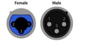 Pin Function
1 Chassis Ground (Cable Shield)
2 Positive Polarity Terminal (Balanced Audio)
3 Negative Polarity Terminal (Balanced Audio)
¼ (6.35 mm) TRS (balanced) Plug
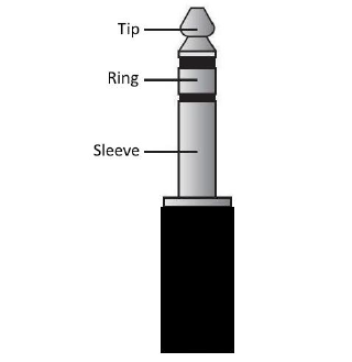
TRS Pin Equivalent XLR Pin Function
Tip 2 Positive Polarity Pin
Ring 3 Negative Polarity Pin
Sleeve 1 Ground Pin (Shield)
Setup
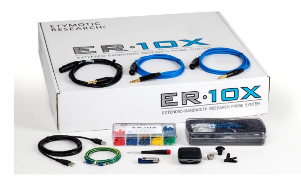
Unpacking the System
The following is a list of parts shipped with each ER·10X system:
- (1) Control Unit
- (1) Probe Kit
- (1) AC Power Supply Cable (US)
- (1) AC Power Supply Cable (Europe)
- (2) XLR Male to ¼” (6.35 mm) TRS Cable
- (1) XLR Female to ¼” (6.35 mm) TRS Cable
- (1) USB A-to-B Cable, 2m (6 foot)
- (1) Ground Cable
- (1) Box of Single-Use Eartips
- (1) Hex Screwdriver
- (1) GRAS Coupler Adapter
- (1) Calibrator Adapter for Probe Eartip (Figure 9)
- (1) USB Flash Drive (Includes Operating Instructions and PC Software)
- (1) User Manual
Probe Kit:
- (1) Probe
- (1) Microphone Shaft Screw
- (1) Package of Probe Tubes
- (1) Shirt Clip
Sanibel Silicone Eartips Sample Kit contains 130 tips total (various sizes: 3mm to 15mm). [3-5mm, 4-7mm, 7mm, 8mm, 9mm, 10mm, 11mm, 12mm, 13mm, 15mm] If any parts are missing, contact your special equipment distributor or ERI by phone at (847) 228-0006 during normal business hours or by email at customer-service@etymotic.com. We recommend that you save the shipping box and packing materials in case you need to store or ship the system. Optional accessories for the ER·10X include an additional probe, probe tubes, and replacement ear tips. An additional probe may be ordered from Etymotic Research, Inc. Probe tubes and ear tips may be ordered directly from Sanibel Supply at https://www.sanibelsupply.com.
Installing the Control Unit
Select either an area on a tabletop or an empty rack slot to install the system hardware. The target location must be level, clear of debris, near a free power receptacle, and provide easy access to the front and rear of the system. Place the control unit in the selected area and mount the hardware in place if applicable. Ensure that both the front and rear POWER switches are in their off (down) positions. Firmly insert the socket of the power cable into the IEC power connection on the rear of the control unit. Firmly insert the plug end of the power cable into the nearest power receptacle which provides AC power at between 100 and 240 VAC at 50 to 60 Hz. Ensure that the system is properly grounded, and then flip the rear POWER switch to the on (up) position.
Installing the Probe
Turn off the ER·10X system, and then insert the probe connector into the socket on the front of the control unit (Figure 6). The plug will fit in only one direction. It will snap in place when inserted properly. To remove the probe, shut off the ER-10X system, and then pull backward on the knurled connector shell. Take note that the system can handle hot-swapping probes, but this is not recommended.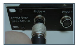
Removing the Calibrator Adapter
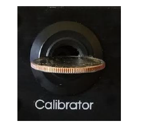
To remove the calibrator adapter, use a coin to align the slot shown in Figure 9 to the horizontal position. This should unlock the adapter from the front panel of the ER·10X instrument.
Control Unit Operating Instructions
Preparing the Subject for Testing
An otoscopic examination of the subject’s ear canals should be performed prior to testing. Excessive cerumen or vernix in the ear canals may interfere with the test and give invalid or incomplete results. Subjects with excessive cerumen, debris, or foreign bodies in the ear canals should be referred to an audiologist or physician for removal of the blockage prior to testing.
Turning On the Instrument
The power indicator light will remain on when power is being supplied to the hardware. The Splash Screen (Display 1) will appear briefly. All LEDs will remain on as the splash screen is displayed. Once the splash screen is no longer visible, all indicator LEDs will enter their normal operating states.

User Settings
The following lists the user-changeable settings on the control unit. These settings may be changed directly on the hardware or from a PC through the USB interface.
- Heaters
Each probe contains a heating element. Calibrators that contain temperature control circuitry will also contain a heating element. The heaters of each connected probe and calibrator may be independently controlled. The heaters for probe B and the calibrator may be configured to match the set point of probe A. - Microphone Gain
The microphone gain on the plugin module may be set to between 0 and 40 dB in 1 dB steps. See the microphone path block diagram in Appendix C. - Microphone Response
The plugin module contains separate electrical paths for 3 different passive filters: high pass, flat, and custom. These electrical paths are selected using mechanical relays on the plugin module. The custom path is not populated by the factory, so it is up to the user to have components soldered into that path; otherwise, this path will remain open. See the microphone path block diagram in Appendix C for information on the filter construction. - Output Limiter
Each driver is attenuated by about 15 dB using 150-ohm resistors when the output limiter is enabled. Confirmation is always provided when the output limiter is disabled and also on each subsequent boot of the system thereafter until the output limiter is enabled. The confirmation is to ensure that the user is conscious that the receivers are being driven at their full potential. Mechanical relays within the plugin module short each 150-ohm resistor once the output limiter is disabled and confirmed. See the driver path block diagram in Appendix C for information on the output limiter construction. - Probe Measurement Refresh Rate for Temperature and Humidity
The refresh rate may be set to every 0.5 seconds (automatic fast), every 2.5 seconds (automatic slow), or on the manual trigger. The reason for this setting is to be able to reduce the risk of noise being added to the analog signal of the probe due to serial communication. The automatic fast setting runs the serial communication at its fastest speed of 35 kHz. This is recommended if serial communication noise is not apparent in acoustic measurements. The automatic slow setting slows the serial BAUD rate to 50Hz, which may help to reduce noise while still providing measurements and allowing the probe heater to function. - Positions
There are three sets of calibrator positions stored on the memory of the ER·10X control unit. Group 4 provides 4 positions, group 5 provides 5 positions, and Group 6 provides 6 positions. Each group contains a set of distinct positions, so a total of 15 positions are stored in memory. These positions are used to create cavity sizes in the calibrator tube during the calibration sequence. - Display Units
The temperature display unit may be set to either Celsius or Fahrenheit. The calibrator display unit may be set to Millimeters, Inches, or Cubic Centimeters. The bore diameter calibration stored in system memory as Inches is used to determine values in Cubic Centimeters. By default, this value is 0.3125 Inches.
Control Panel
The ER·10X instrument uses 7 buttons to control all functions of the instrument (Figure 10). These buttons are arranged in a directional cursor format (LEFT, RIGHT, UP, DOWN, START, ENTER and CANCEL).
 Calibrator Tuning
The Calibrator Tuning initialization process (Display 2) is executed after the boot sequence is completed, following the splash screen.
 Main Menu
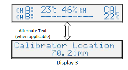
The attached probe status and calibrator temperature are shown on the Main Menu (Display 3). The temperature and relative humidity of each connected probe will be displayed.
 Calibrator Temperature Menu
If the calibrator is equipped with temperature control circuitry and no calibrator error has occurred, the temperature of the front and rear calibrator sensors are displayed on this menu (Display 4). The average of these two temperatures is displayed on the Main Menu (Display 3).

Probe Heater Menu
The probe heater set-points are shown on this menu (Display 5). The probe heater may be set to off, or set to a temperature between 26.7°C and 40.6°C (80°F and 105°F). Probe B may also be configured to match whatever value is set for probe A. Press ENTER to set the probe heater temperatures.
 Calibrator Heater Menu
The calibrator heater set-point is shown on this menu (Display 6). The bottom line will show “Not Equipped” and this heater value cannot be changed if there is no temperature control circuitry in the installed calibrator. Otherwise, the calibrator heater may be set to off, matched to the set-point of probe A, or set to a temperature between 26.7°C and 40.6°C (80°F and 105°F). Press ENTER to set the heater temperature.
 Microphone Gain Menu
The microphone gain is shown on this menu (Display 7). The gain can be set between 0 and 40 dB. Press ENTER to set the gain. Microphone Response Menu
The microphone response settings are shown on this menu (Display 8). The mic response for each probe can be set to High Pass, Flat, or Custom. Press ENTER to set the microphone response. Output Limiter Menu
The output limiter setting is shown on this menu (Display 9). This value may either be enabled or disabled. Press ENTER to set the output limiter.
Probe Measurement Refresh Rate Menu
The probe measurement refresh rate is shown on this menu (Display 10). This value may be set to automatic-fast, automatic-slow, or manual. Press ENTER to set the probe measurement refresh rate.
Calibrator Positions Group Menu
The calibrator positions group is set using this menu (Display 11). This allows the selection of 4, 5, or 6 positions. Press ENTER to set the positions group. Calibrator Position Menu
Calibrator positions are set through this menu (Display 12). Press ENTER to set the positions of the selected group.
Temperature and Calibrator Units Menu
The Temperature and Calibrator units are shown on this menu (Display 13). The Temperature units can be either °C or °F. The Calibrator units can be one of Millimeters (mm), Inches (in), or Cubic Centimeters (cc). Press ENTER to set the temperature and calibrator units. Buzzer Control Menu
The Buzzer Control setting is shown on this menu (Display 14). This value may either be on or off. Press ENTER to show the Buzzer Control set menu. Hardware Information Menu
The ER·10X controller serial is shown on this menu (Display 15). Press ENTER to show more hardware information details such as probe and module serial numbers, probe service dates, and module revision numbers. Use the LEFT or RIGHT arrow buttons to parse though this information. Firmware Information Menu
The controller firmware version number is shown on this menu (Display 16). Press ENTER to show more version details. Use the LEFT or RIGHT arrow buttons to parse through the system build date, module firmware versions, and calibrator firmware version. System Status Menu
The current system status is displayed on this menu (Display 17). There are three possible conditions: Ready, Waiting, or Error.
Press ENTER to bring up a list of system errors, if any. Parse through the errors by pressing the LEFT or RIGHT arrow buttons. The text “No system errors detected” will show if no system errors are present. Initial Calibration Sequence Screen
This is what is shown right after the START button is first pressed (Display 18). The value in the upper right is the current location of the calibrator in the selected calibrator unit. Press the ENTER or START button to move to the first position.
Calibration Sequence Moving Screen
This is what is momentarily shown as the calibrator piston is moving to position (Display 19). The bottom line shows to which position index the calibrator is moving and the location for that position index in the selected calibrator unit.
Calibration Sequence at Position Screen
This is what is shown after the calibrator piston has reached a position (Display 20). This is similar to the Initial Calibration Sequence Screen, but the bottom line will alternate showing that the calibrator is at a position. Press the ENTER or START button to move to the next position.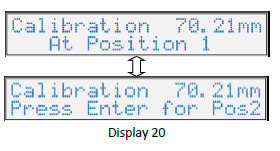
Calibration Sequence Final Position Screen
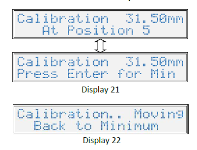
This is what is shown once the calibrator piston has reached the final position in the selected group (Display 21). Pressing the ENTER or START button here will begin the process of moving the calibrator to the minimum location. The text in Display 22 will be shown as the calibrator is moving back to the minimum location. Afterward, the display will go back to showing the System Menu.
ER·10X System Control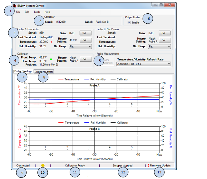
Servicing the Instrument
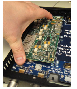
- Remove the five screws holding the top housing of the chassis in place.
- Remove the top housing from the chassis.
- Insert the new plugin module aligning with the sockets Gently apply force evenly to the front connector, then the side connector, and finally the rear connector.
- Push down on all three connectors again to verify that all three connectors are completely seated.
- Attach the screws to the probe module.
- Return the top housing of the chassis in place and screw it in place.
Cleaning and Maintenance
Use a new ear tip for each subject. Eartips are for single use only. The probe tube, which does not make direct contact with the subject, should be replaced if there is any sign of contamination. Disinfection of the probe tube between subjects is not required. External parts of the instrument/probe can be cleaned to remove visible particulate contamination. Unplug the probe from Controller prior to cleaning. Do not attempt to insert any object into the probe.
This instrument requires no regular maintenance beyond routine cleaning and annual calibration. The probe tube requires replacement only when it becomes clogged. A defective product should not be used. Make sure all connections to external accessories are snug and secured properly. Parts that may be broken or missing or are visibly worn, distorted, or contaminated should be replaced immediately with clean, genuine replacement parts manufactured by or available from ERI.
Troubleshooting
Specifications



Performance Data
ER10X USB Control – PC Software Installation
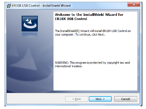
Execute the ER10X Control Setup located on the included flash drive or download the latest version from http://www.er10x.com. The setup will extract the files necessary in order to install the utility.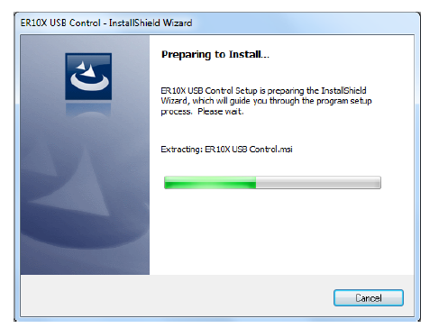 After inflating the necessary files to run the utility, the ER10X Control Setup Wizard will start. To continue, click “Next >”.
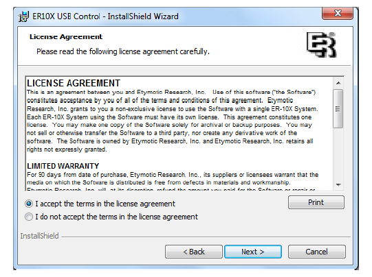
 The License Agreement screen allows you to accept the terms for using this software. You must agree to the terms before continuing with the installation. Click “Next >” to continue after accepting the terms.
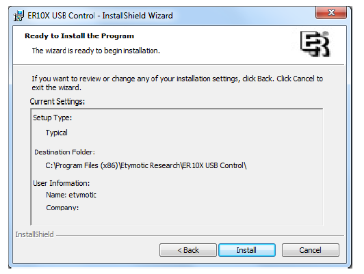
 After you have confirmed your selections, the installer is ready to begin. Press “Install” to begin the installation.
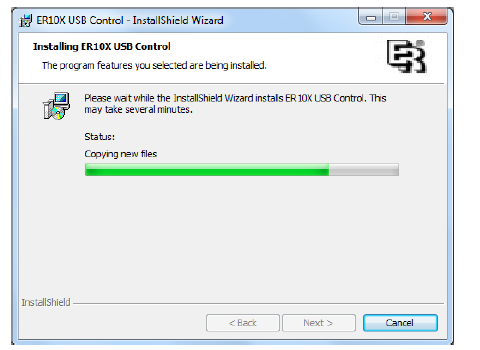
 The installation process may take a few minutes to complete.
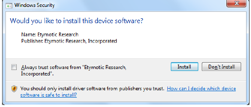
 Windows may ask you to confirm the installation of the ER10X system driver (See Figure F.6). This driver is necessary to use this application. Click “Install” to agree to install this driver.
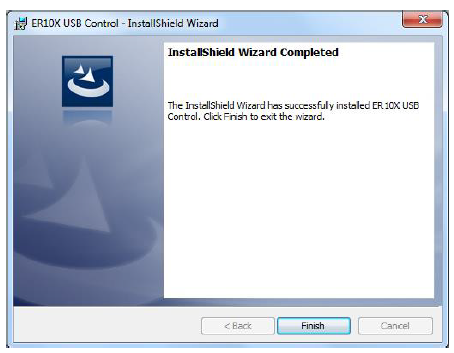
 Click “Finish” on the Install Shield Wizard Completed screen to exit.
FAQs About Etymotic ER10X Hearing Test Instrument
What is the Etymotic ER10X Hearing Test Instrument?
The Etymotic ER10X is a precision hearing test instrument designed for audiologists and hearing professionals. It is used to conduct accurate and reliable pure-tone audiometry tests to assess an individual’s hearing thresholds across different frequencies.
How does the ER10X ensure accuracy in hearing tests?
The ER10X incorporates high-quality balanced armature receivers that provide precise sound output, ensuring accurate and consistent results during hearing assessments. Its advanced technology reduces distortion and maintains signal integrity, allowing for reliable measurements.
What makes the ER10X suitable for audiometric evaluations?
The ER10X is compact and ergonomically designed, making it easy to handle during hearing tests. Its noise-isolating ear tips help block out ambient sounds, creating a controlled testing environment for more accurate evaluations.
Can the ER10X be used for both adult and pediatric hearing assessments?
Yes, the ER10X is versatile and suitable for both adult and pediatric patients. Its calibrated output ensures reliable testing results for individuals of all ages.
Is the ER10X compatible with standard audiometry equipment?
Yes, the ER10X is compatible with most standard audiometry equipment, including audiometers and hearing evaluation systems. It features a standard 3.5mm connector for easy integration.
Does the ER10X require regular calibration?
Yes, like any precision hearing instrument, the ER10X should undergo regular calibration to maintain its accuracy. It is essential to adhere to the manufacturer’s recommended calibration schedule to ensure reliable test results.
Can the ER10X be used for hearing screenings in non-clinical settings?
While the ER10X is primarily designed for professional use by audiologists, it may also be utilized for hearing screenings in non-clinical settings, provided that the tester is trained in administering hearing tests and interpreting the results.
What accessories are included with the ER10X Hearing Test Instrument?
The ER10X typically comes with a set of foam and flanged ear tips in various sizes for optimal patient comfort and noise isolation. It may also include a protective case for safe storage and transportation.
Is the ER10X compatible with computer-based audiometry systems?
Yes, the ER10X can be used with computer-based audiometry systems. It often comes with the necessary adapters or connectivity options to integrate seamlessly with modern technology.
Where can I purchase the Etymotic ER10X Hearing Test Instrument?
The ER10X is available through authorized Etymotic distributors or directly from the Etymotic website. Interested buyers can inquire about purchasing options and pricing from these sources.
For more manuals for Cherry, Visit Manualsdock
[embeddoc url=”https://manualsdock.com/wp-content/uploads/2023/07/Etymotic-ER10X-Hearing-Test-Instrument-User-Manual.pdf” download=”all”]

